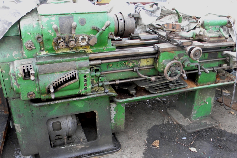
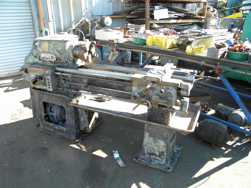
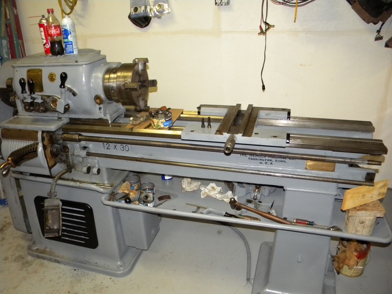
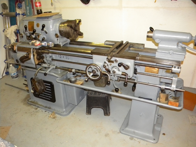
I picked up the contents of a shop and this Hendey lathe was in the back under a tarp.
I didn't need another lathe but this was a Hendey and it appeared to be in fairly good shape so I dragged it home.
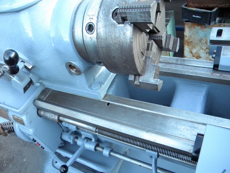
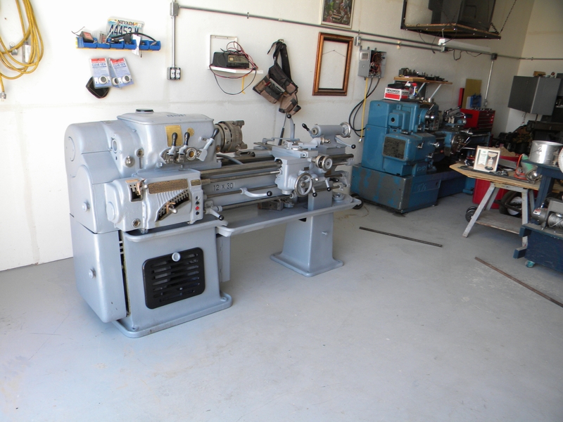
The guy insisted that his guy would repaint it and make it look nice and I was not in a position to refuse. Here is the stripped version.
A closeup of the painted version. As will be seen later you can't rely on a pretty face.
Unloading the machine from the truck. That's me as the counterweight (finally found something I'm qualified for) The machine weighs in at
around 2900 lbs and with a 3000 lb fork we had just enough to drag it to the edge of the truck where we could get a good bite on it.
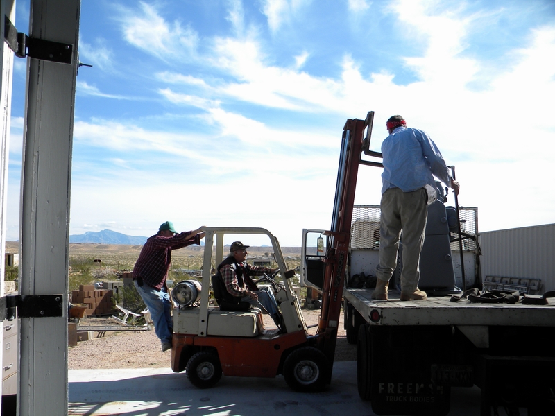
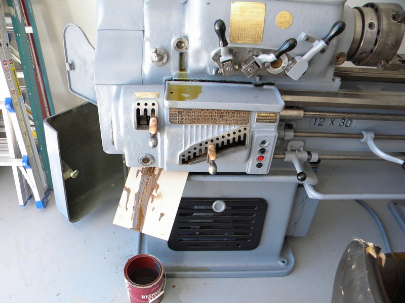
There. In place and ready for inspection. Looks nice doesn't it?
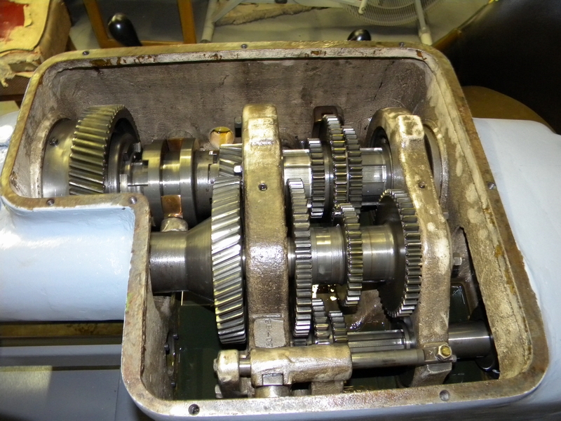
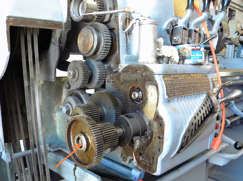
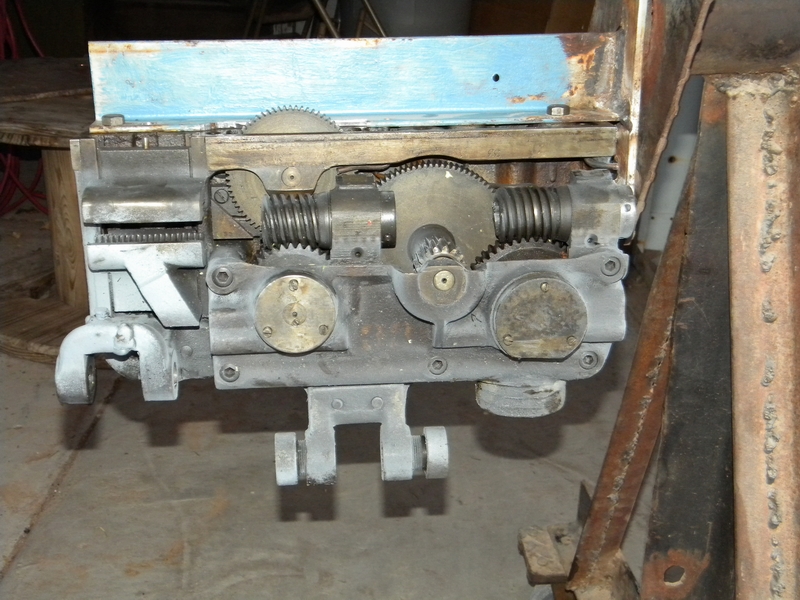
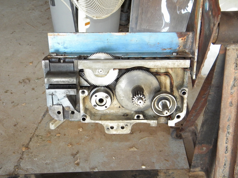
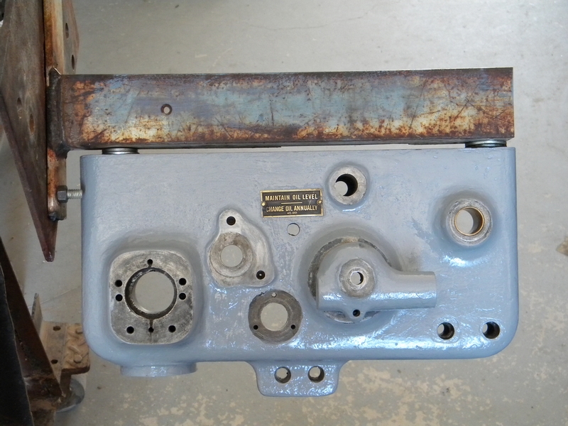
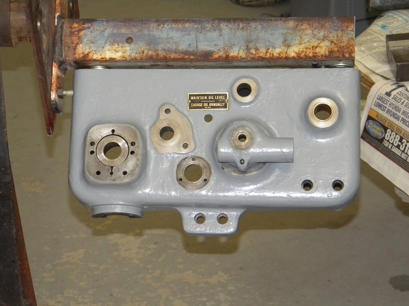
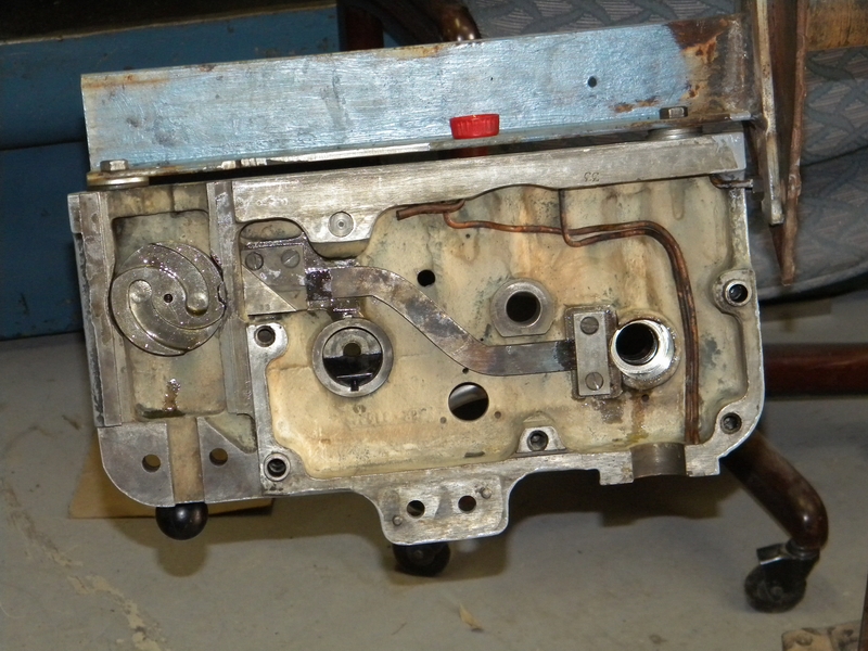
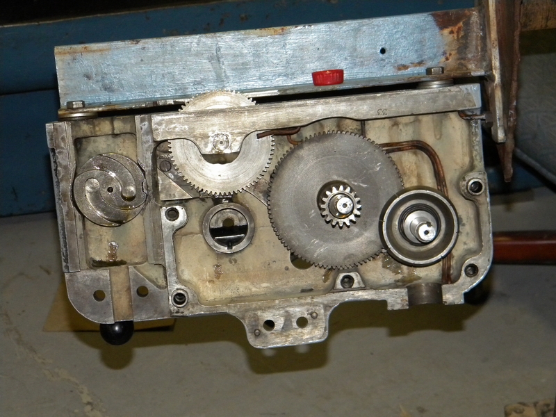
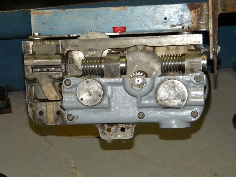
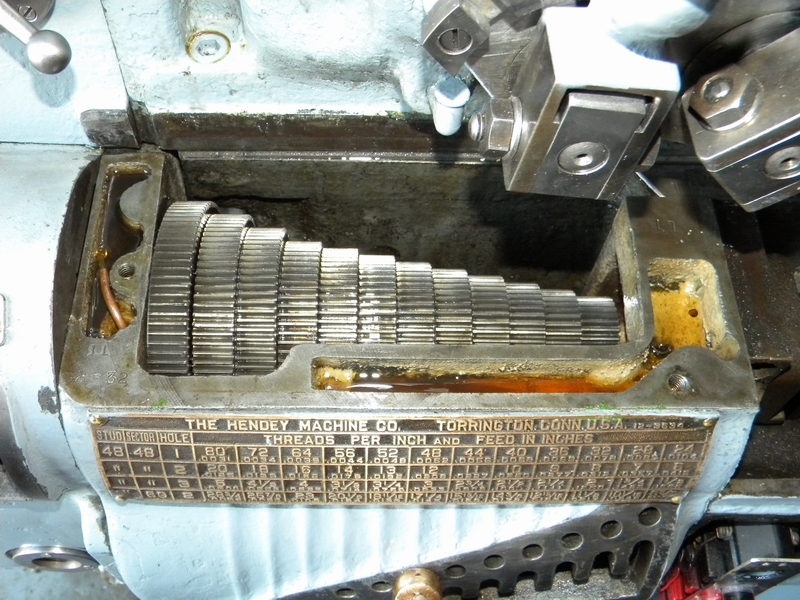
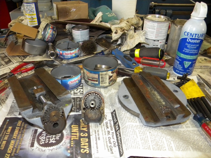
First up and most important is the gearbox. Dirty but the gears look good, Needs a rinse and a change of oil.
We are not so lucky on the leadscrew gearing tho. there was a lot of swarf in the gears and it had peened over the tips of several teeth
making it bind in spots.
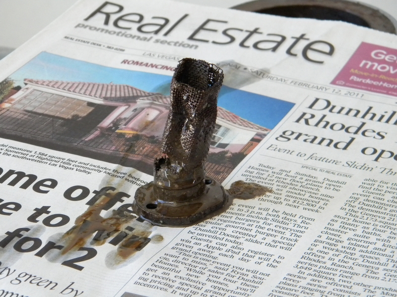
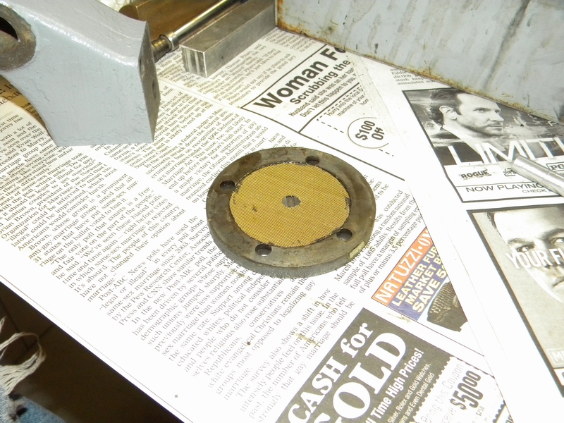
I pulled the filter out to drain the leadscrew trans and this is all I got. Notice the amount on top from the rear spindle bearing.
Not too impressed with the filter, gonna have to make something up. The local Ace hardware does not carry these anymore.
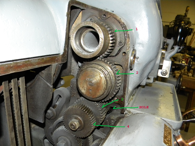
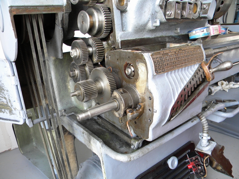
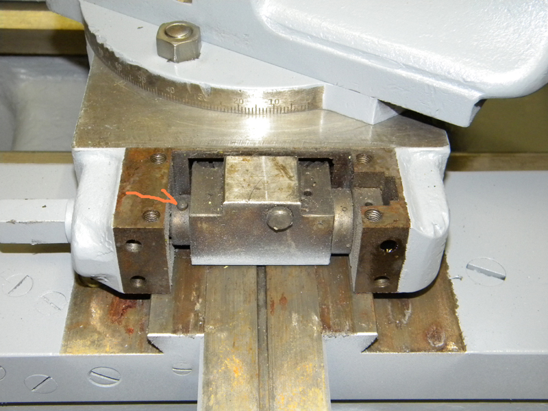
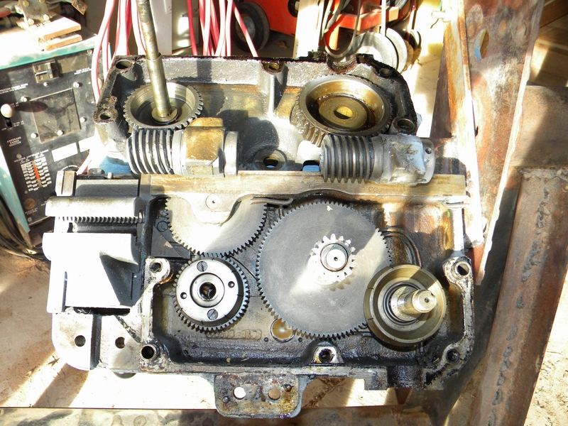
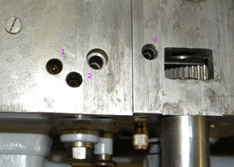
This is where Hendey breaks away from the pack with their bevel gears used to drive the leadscrew drive train. I was a little confused at first.
The shift gear (2) would engage the spindle gear (1) but it only turned a third gear (3) that went nowhere.
It was then that I realized that gear 3 is attached to an outer concentric shaft that goes under the headstock to the bevel gears that enable the forward and reverse.
The inner concentric shaft is attached to a fourth gear (4) that turns the transmission. Gear 4 and its mate also have a lot of junk stuck in the teeth
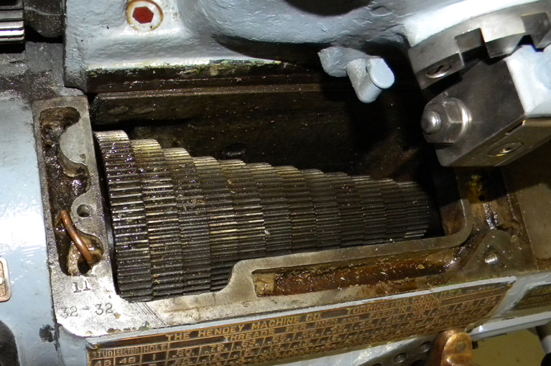
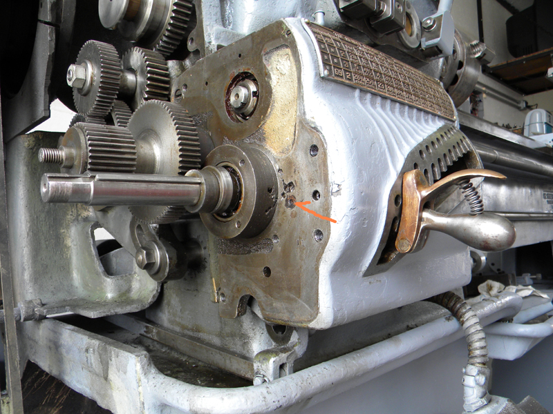
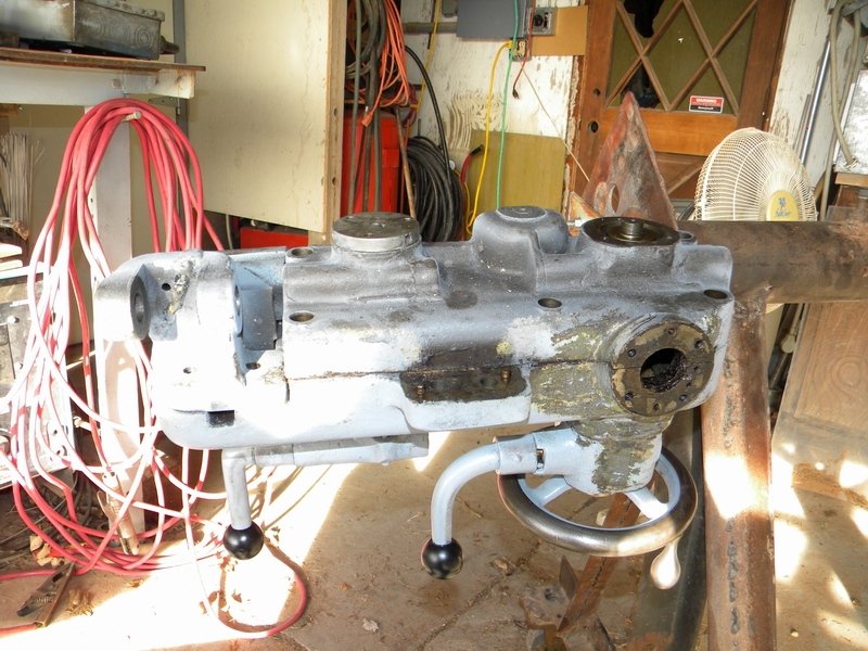
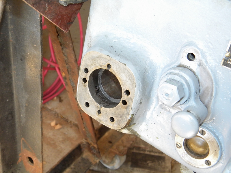
I could not find a decent place to check the bevel gears, they are barely visible thru the hole shown.
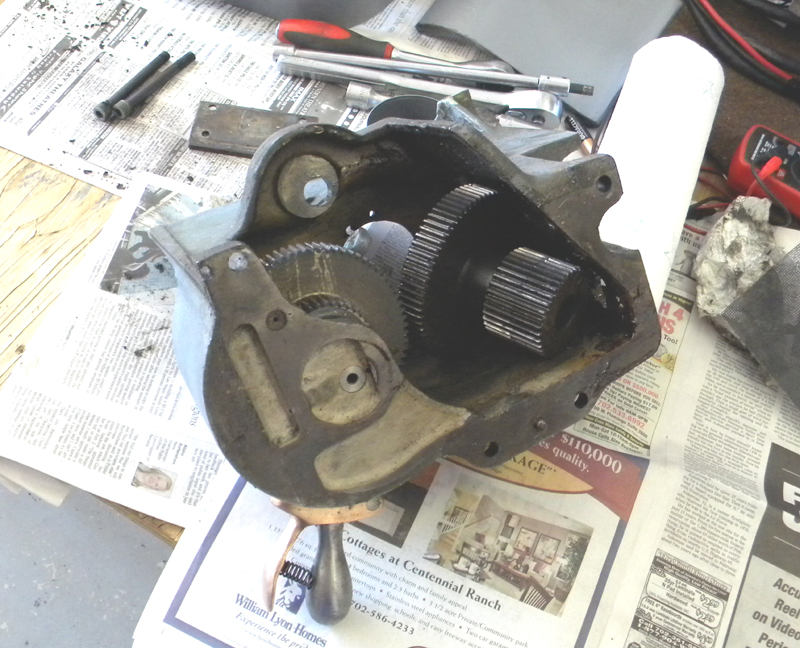
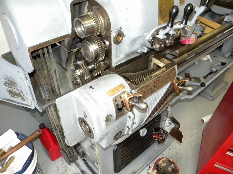
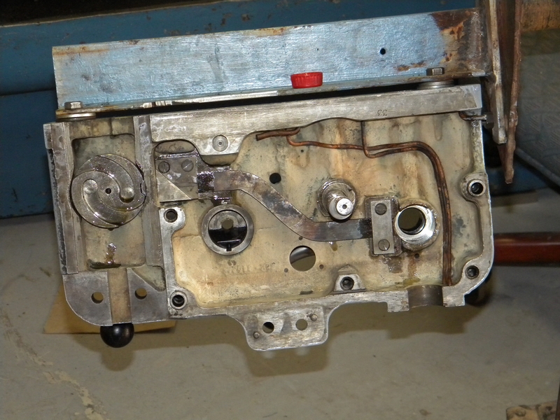
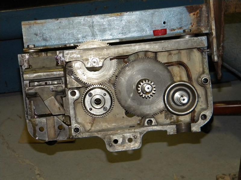
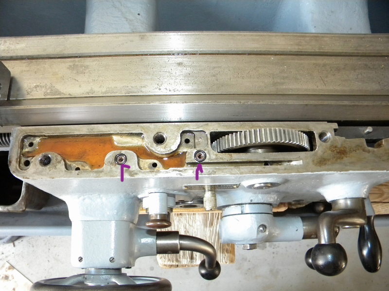
Looking inside I see a lot of junk in the gears that is impossible to remove so I'll have to remove the three speed part of the trans for thorough cleaning.
Removing the fasteners shown gets me there but there is a loose gear that must be removed with the unit. Here it is in its proper place.
The arrow is where the fine thread nut belongs. You can also see some of the junk in the gear teeth.
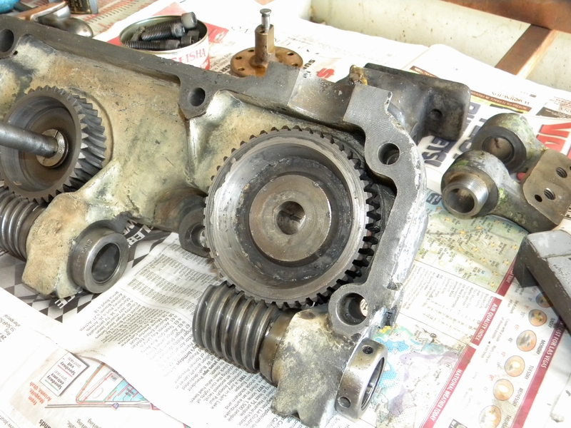
Here is the 3 speed trans with the gear that has to come with it.
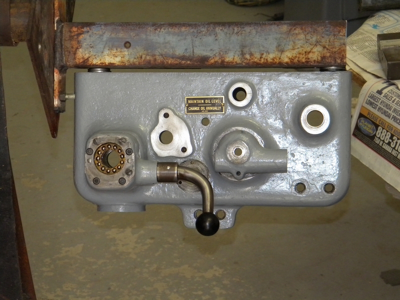
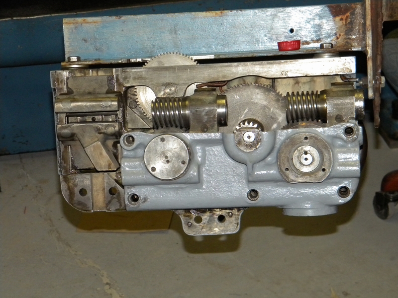
Here is the oil pump. It appears to have been repaired or modified, it pumps oil fine although the pickup tube will have to be straightened.
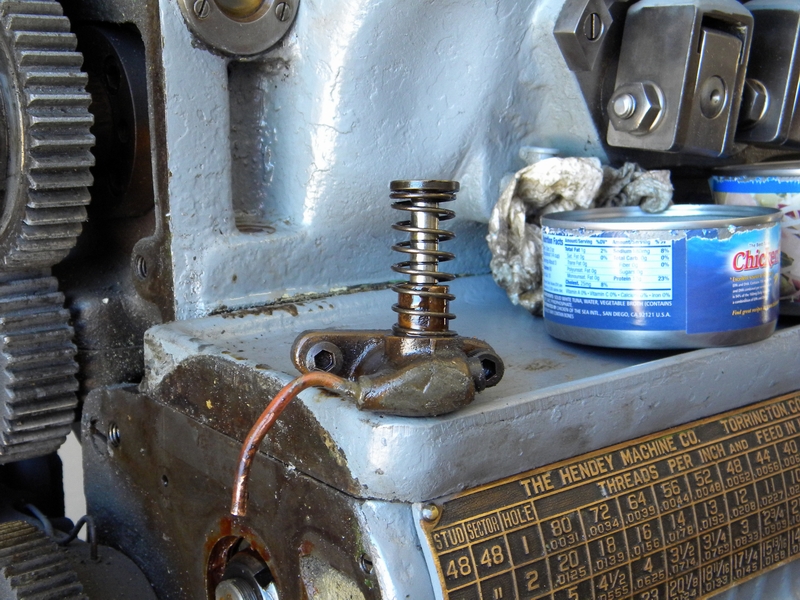
The arrow shows where the oil under pressure is forced up to the resorvoir above where it is distributed thru a series of channels and tubes
to the gears in the 3 and 12 speed boxes and the lower gear bushings on the side gears.
Around it you can see several casting flaws. I've seen several of these in other places on the machine, all of them in non-critical spots.
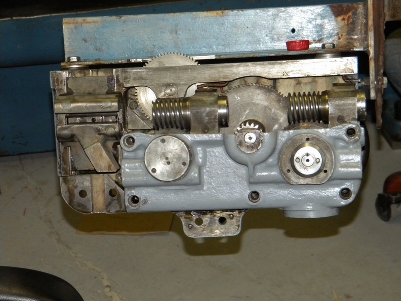
Here the oil pump and eccentric housing is installed. You can also see the brass tube used to force the oil into the side gear bushings.
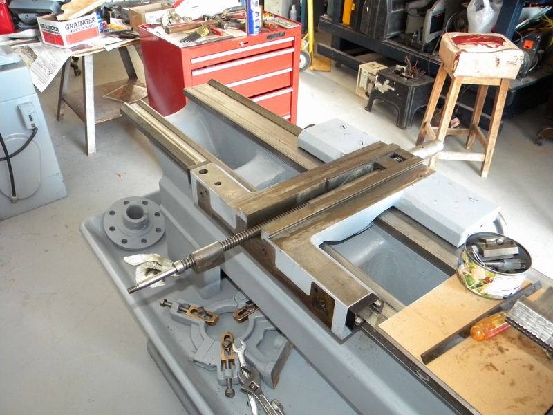
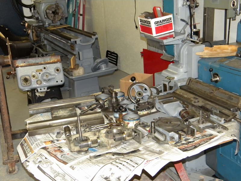
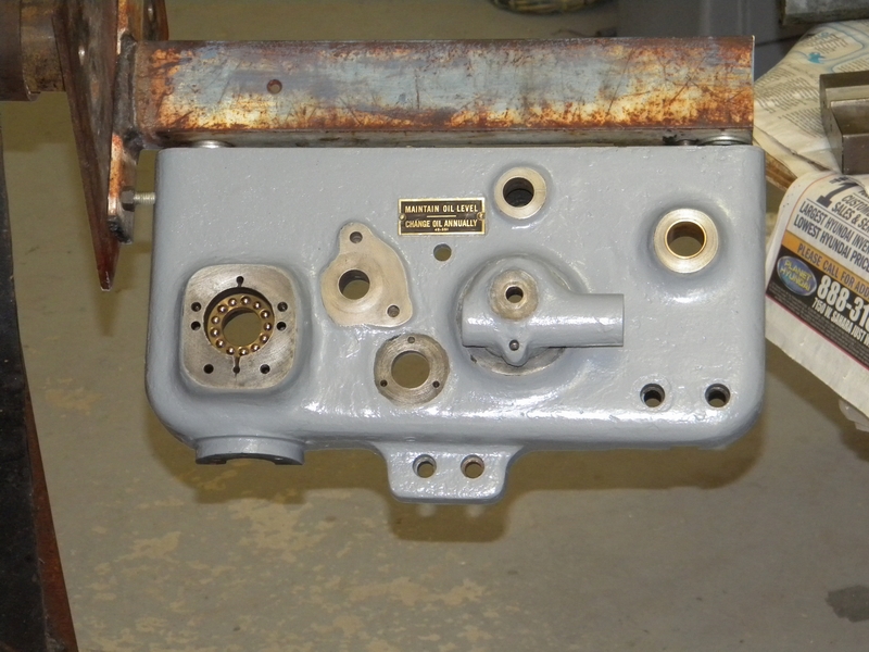
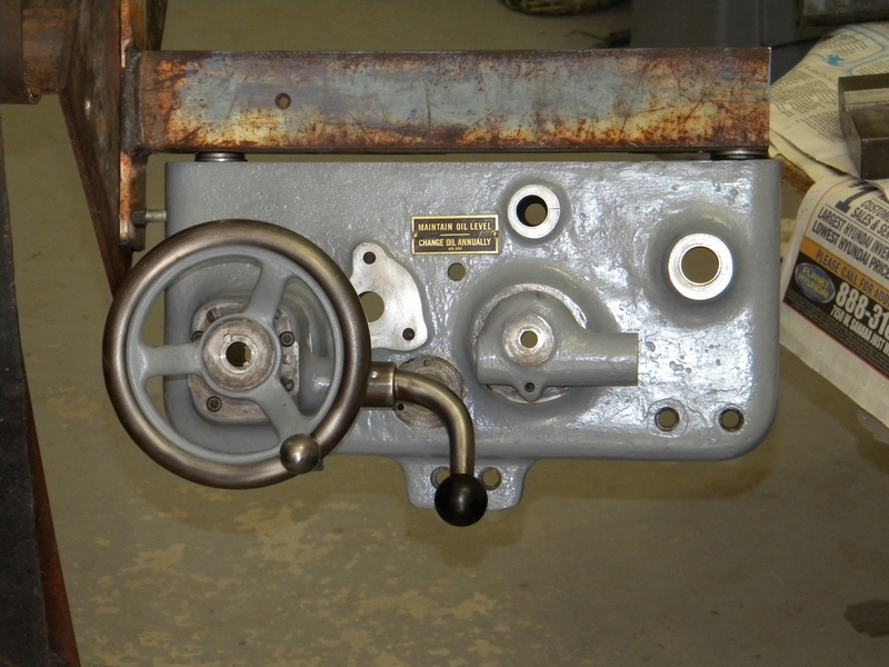
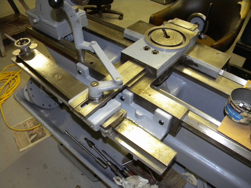
The transmission is back in place all cleaned up and ready to run some oil thru it. On to the carriage.
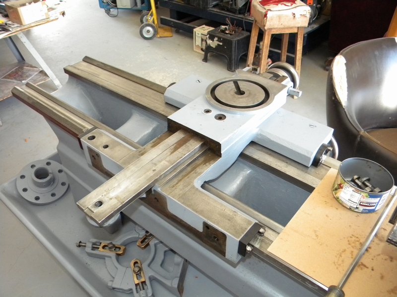
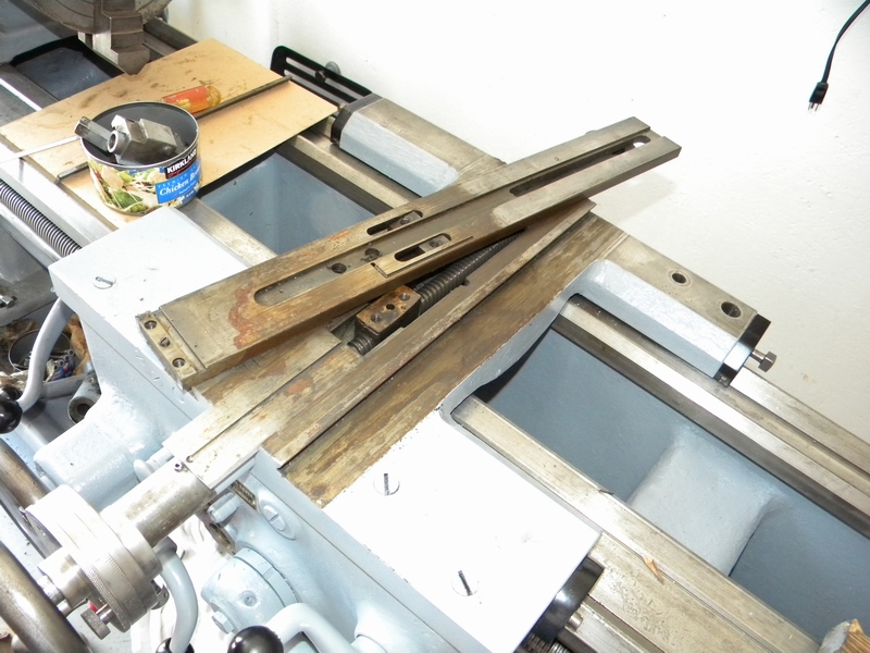
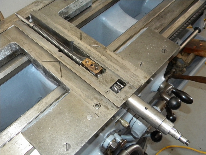
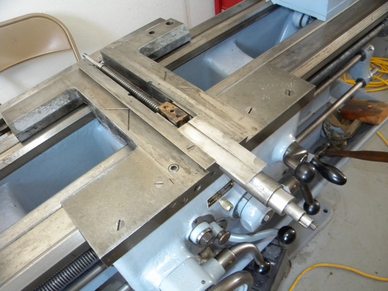
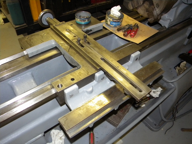
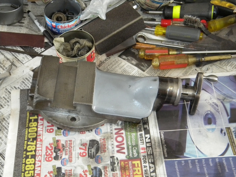
Time to clean up the carriage. We'll start with the taper attachment.
Not so pretty underneath. I knew the condition of the lathe before repainting and did not want the painter to go any deeper than he did.
He saved me a lot of work and did a great job but this is an excellent example of check carefully before purchase.
I would have been upset if I had paid real money for this unit.
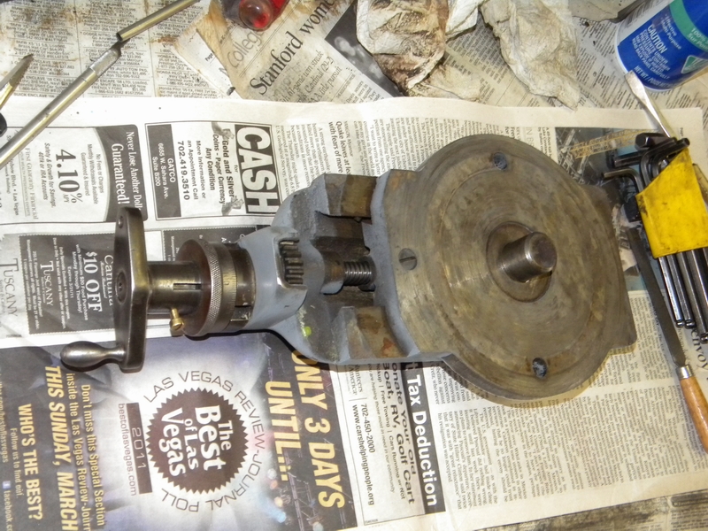
The taper attachment is off and ready to be cleaned.
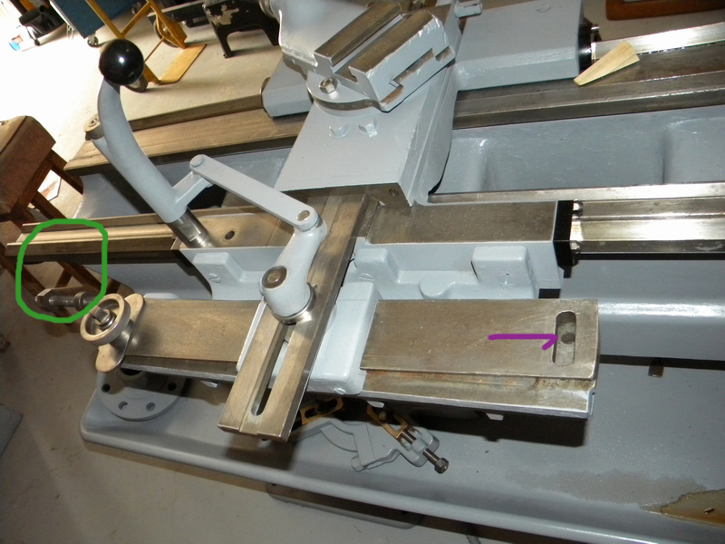
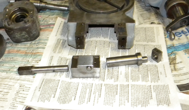
Now the quick withdraw cam is removed by tapping out a taper pin on the inside left of the cam.
Remove the 2 bolts above the circle.
Now the top slide can be moved back revealing the taper slide.
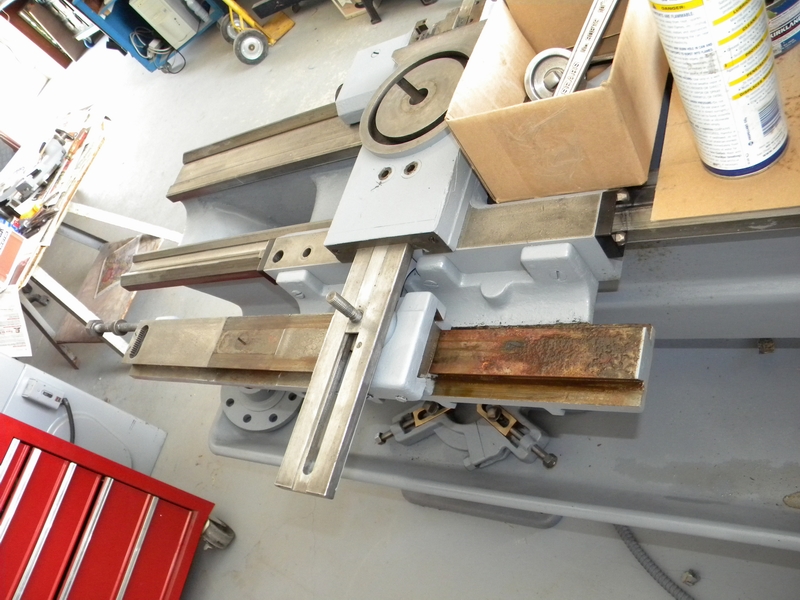
Taper slide released.
Now the front handle can be removed and the screw removed from the back.
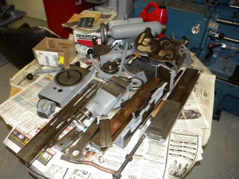
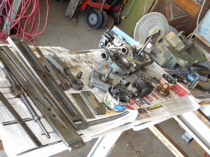
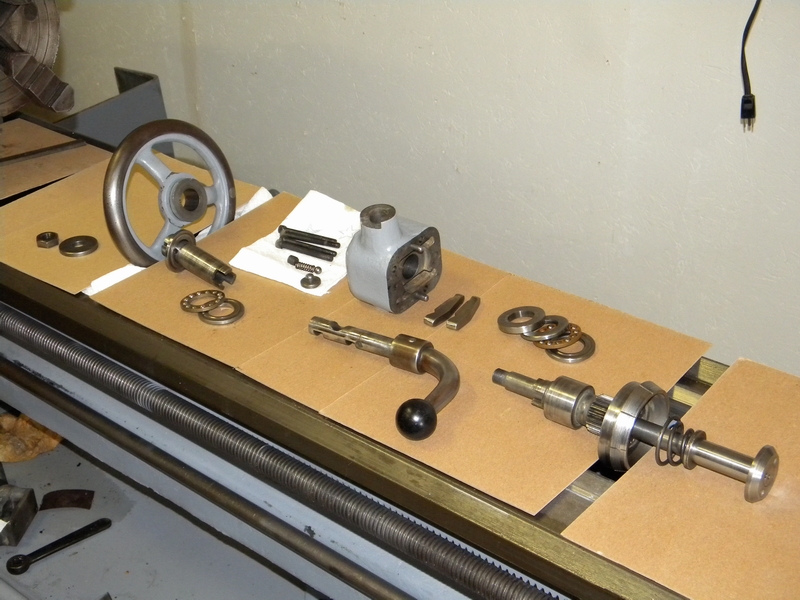
Laid out and ready for cleaning.
After several requests here is the exploded view of the quick withdraw cam setup. This is held together with the taper pin shown above.
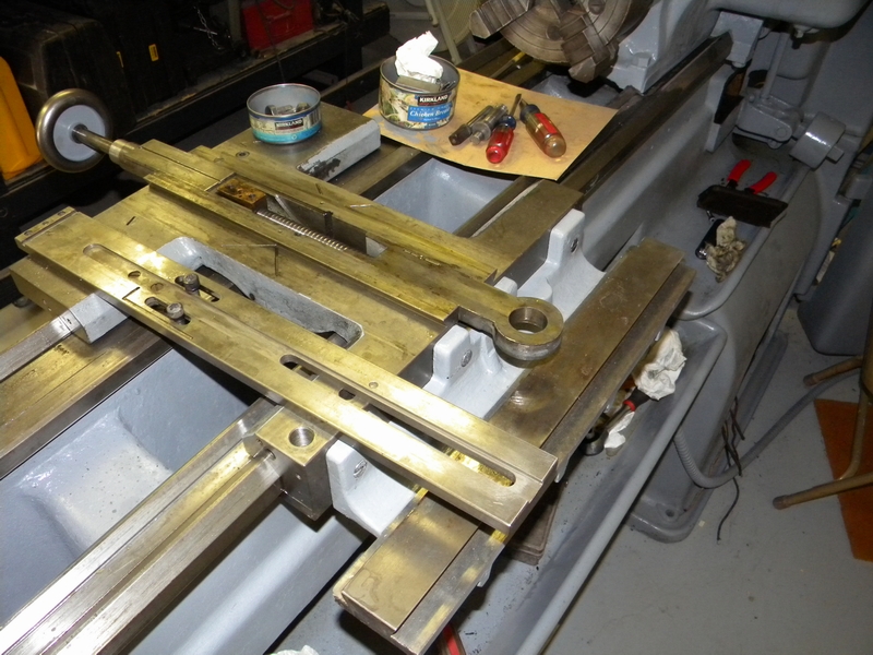
I had to remove the apron to get that misplaced lever on the middle bar off so I might as well clean it up and check it.
Here is the apron mounted on a Hendey approved apron holder that was modified from a DSG apron holder.
Here we are using the tilt feature of the apron holder to access and remove the oil pump so the case halves can be split.
The nut on the longitudinal feed shaft also had to be removed along with the the nut for the crossfeed shaft on the front .
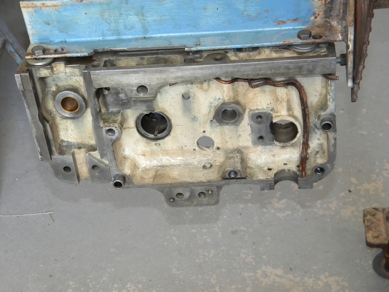
Here the case is split with the back half rolled over and lying on top.
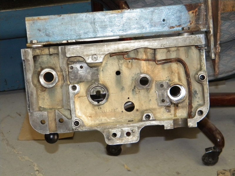
Cleaned all the gunk out of the case. It appears that this unit was not used for a while and the remaining oil was allowed to evaporate.
You can see the oil lines going up to feed the carriage which then drains to the reservoir above on the right and then to the bearings.
Here the semi-clean parts are laid out for further checking.
It looks like the longitudinal clutch has been repaired. For the amount of mess involved I'm just going to clean it up and hope for the best.
It seemed to grab OK when I checked it before disassembly, the other half looks good and this half seems to mate up OK.
Here the two clutches and the longitudinal gear are partially removed to get at the back part.
This is the front bearing and clutch engagement part for the longitudinal feed. Note the oil holes on the top and bottom.
The oil flows from the resorvoir above, thru the bearing and then out the drain hole in the bottom back to the sump.
There is plumbing like this throughout the apron and in the gearboxes.
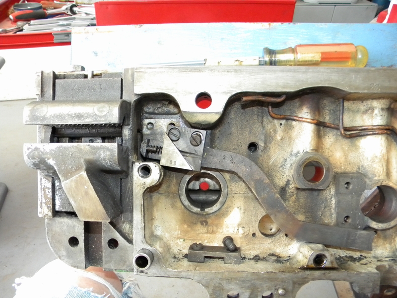
Ready to remove the cross slide gear and half nut lockout.

Here the half nut lockout is removed.
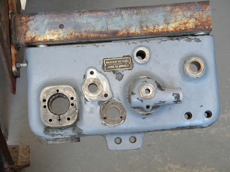
Remove the half nuts and the front half is now clean and ready to go. The oil reservoir can be seen better in this shot.
Got the front ready for paint.
Ready for assembly.
Got the guts of the apron cleaned and laid out
The longitudinal feed clutch and bearing setup took a while to figure out so it would work properly. I have it laid out here in approximate order.
The bearing races are marked as tho they are identical but the race that goes on the clutch shaft and the race that abuts the handwheel have a smaller internal diameter.
The rockers go in with the small end on the adjustment screws. The detent ball and spring and bolt for the retention of the lever completes the setup.
First (small ID) race in place with the bearings.
Large ID race and thrust washer in place.
Here the front clutch assembly is installed with a large dia race and bearings.
Hand wheel on and ready for assembly in the rear.
This rear view shows the two tubes from the oil pump that feed the carriage lube system.
The right hand one feeds the ways and the left feeds the crosslide. The short ones are for lubing the two worm shafts shown later.
Half nut engagement mechanism with lockout installed.
Longitudinal gear eccentric installed.
Crosslide gear in place.
Here the longitudinal gear is placed on the eccentric.
The longitudinal gear has to be slid off and engaged with its mating clutch shaft and slid in together.
Crosslide clutch and half nuts in place.
Back is in place. I didn't use any permatex here because I was afraid it would make it too hard to separate later.
Nut on longitudinal shaft with securing setscrew in place.
Nut cover in place. I later turned the 2 copper feeds so they would dump oil on the bearing felts for the worm shafts.
Finished front. there is a nut holding the crosslide clutch shaft that is not shown.
The oil level window is easier to install first but I didn't have the necessary window material till later.
Here is the underside of the carriage. Oil under pressure comes in thru holes 1 and 3 and feeds into the two holes drilled at 2 for way lubrication
and hole 4 for crosslide lube. The excess drains out 5 and 6 into the reservoir where it is distributed throughout the apron.
I thought at first the oil was under pressure to the ways and crosslide and was wondering how the pressure was maintained to them with an
open hole at 5 & 6. I was thinking it needed some missing jets at 5 & 6 till I flipped the carriage over and realized that once the oil gets to the carriage
it is a gravity system and the oil into the reservoir is governed by the height of an orifice accessed from the top. Took quite a while to clean all the passages.
Hole 7 is just a blind tapped hole, for an accessory?
Meanwhile here is a bottom view of the oil pump. I just had the filter cover on to keep out dirt but now I had some filter screen to install.
The screen is cut to size but it likes to curl so I used Permatex on the edge to hold it on the cover.
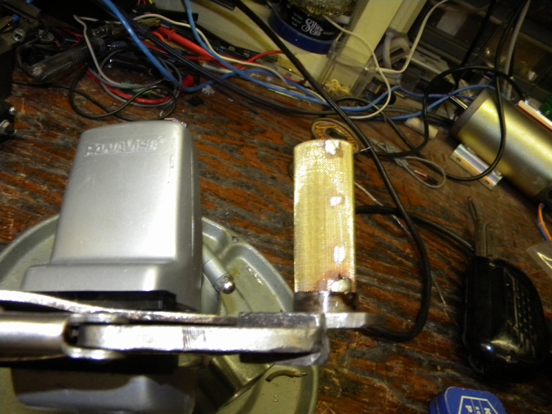
I also made up the filter for the leadscrew transmission and soldered it to its cover.
After installing the oil pump I disengaged the longitudinal feed and cranked the handle to pump some oil to the galleys that feed the ways and crosslide.
after a bit the oil was coming up from hole 1, overflowing to 2 and going out to the ways. However there was no oil to 3 that fed the crosslide.
After bracing the apron and removing the carriage I noticed that the area at the top of the oil delivery tubes would be a nice place for
O-rings. There was also another casting flaw just above the right arrow allowing the oil to leak into the reservoir.
After reinstalling the pump and carriage I now have oil to the crosslide.
Now I can finally replace the bottom rod, but first I had to play with what turns out to be the kick-out lever for disengaging the feed.
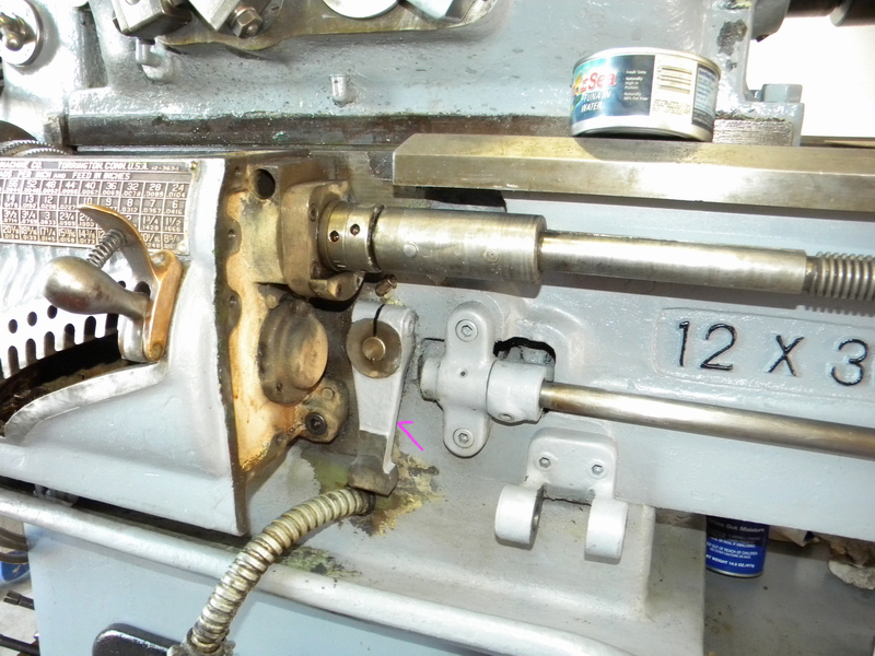
Bottom rod replaced and everything seems to be working properly. The shift lever for the carriage direction seems a little stiff but usable.
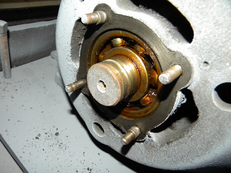
Carefully popped the endcap off of the motor to check the bearings before powering it up.
The grease is a bit old but the motor turns fine so I'll add some new bearing grease and run it for now.
When the lathe is moved I'll pull the motor and clean and regrease.
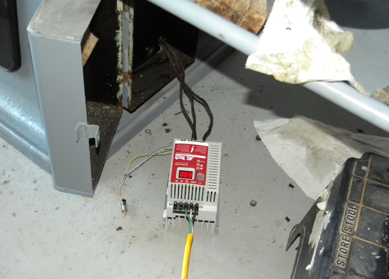
Got the VFD set up and connected and fired the lathe up.
For lack of proper info I put Vactra 2 in the gearboxes and apron with DTE 24 in the headstock and spindle.
It looks like we have proper oiling on the left and the right sides of the trans.
The tube on the left squirts heavily and the one that feeds the upper and lower bearings and drool tube on the right oozes nice.
It is interesting how Hendey regulates oil flow with orfice size and height.
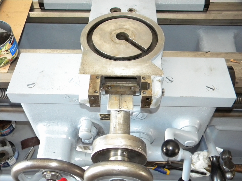
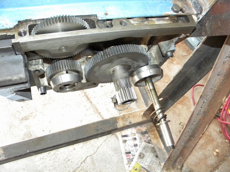
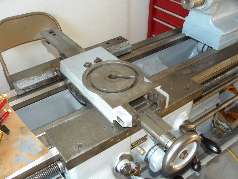
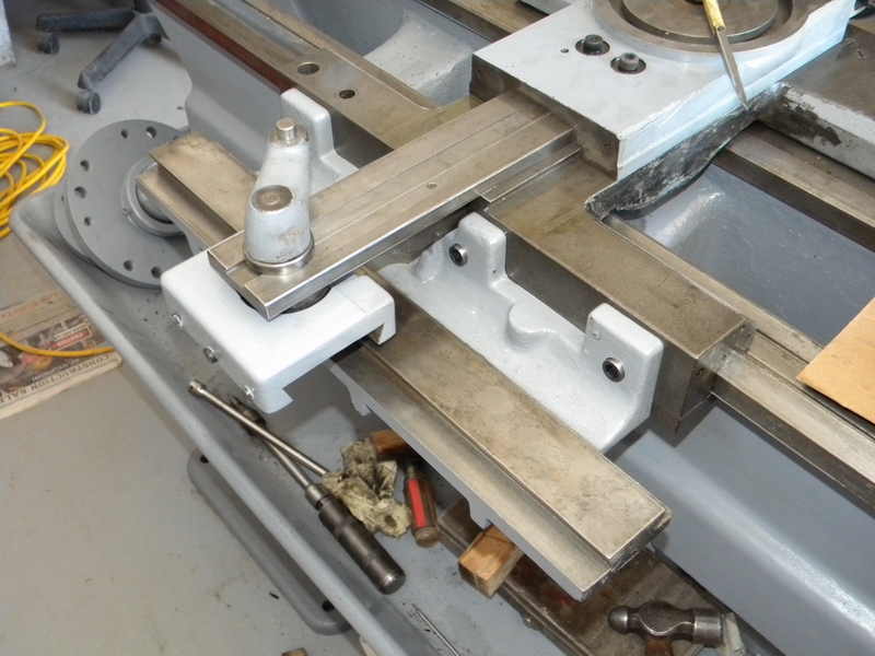
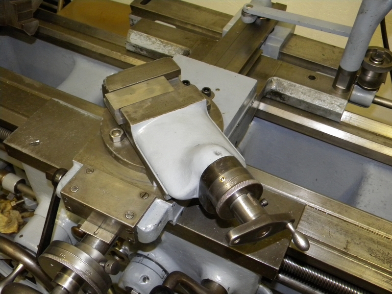
Finally getting to the carriage. Getting the gear lined up on the leadscrew shaft was fun. I finally marked the key position on the gear for reference.
Plenty of oil and then a cover plate.
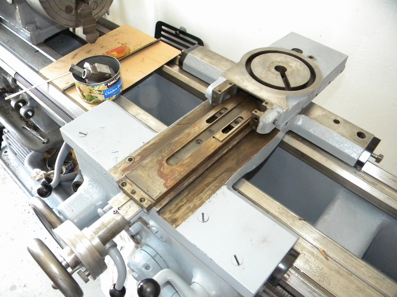
Here the taper attachment sliding thingy (technical term) is attached to the leadscrew.
I had mistakenly mounted the taper support in the hope of not having to juggle it later but had to remove it to fasten the carriage slider.
When I installed the slider for the taper I found that 2 bolts were necessary to hold the T-nuts to keep them from sliding off.
Lower part of the compound rest in place bolted to T-nuts.
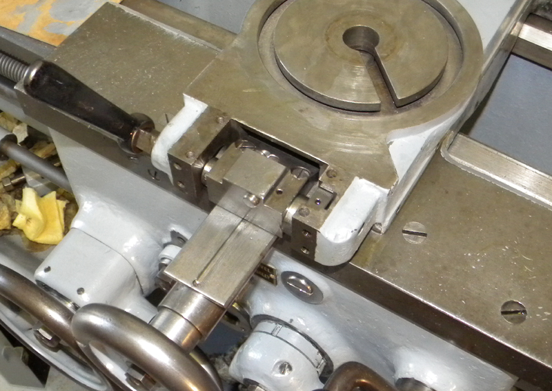
Quick withdraw installed. Couldn't move it before but it slides nice now.
Here we have the taper support off and the taper slider in place.
The support had to be off so the taper slider could be installed. It also allowed the carriage slider nut to be fastened easier.
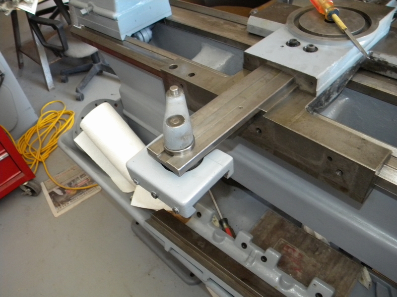
Taper support back in place. I didn't like fooling with the Hendey screwdriver bolts so I fastened it with allen head bolts.
Mounted the slider and the quick tightening handle. When I reassembled I painted the moving parts with 50W way oil.
Because of wear the handle does not tighten properly so I had to use a thin washer under the arm on the slider.
Here the slider is being installed. The gibs are then oiled and slid into place.
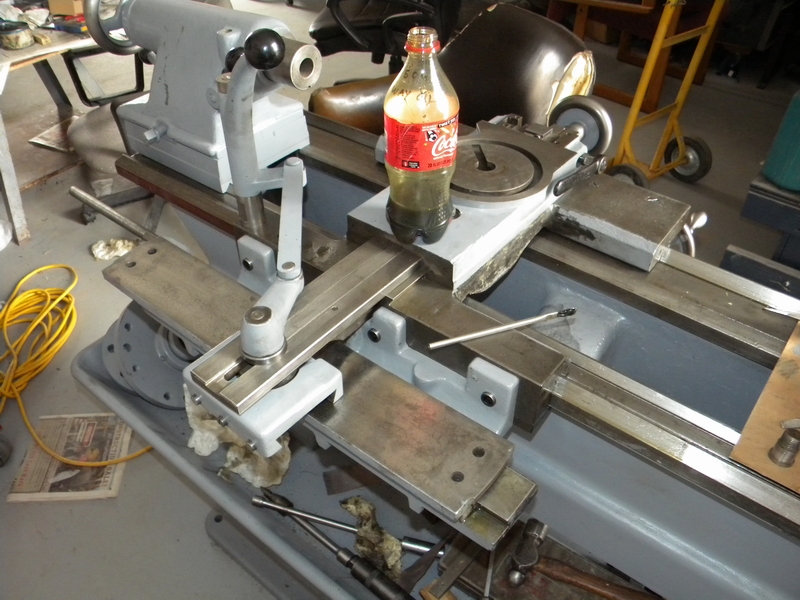
Finally getting to the compound rest. It does not turn easily and needs cleanup.
Mostly apart and ready for cleanup. The gib is broken and missing about 2" I'll have to find one or make one.
Back together and ready to install. I'll leave the compound slide tightened down until I can get another gib.
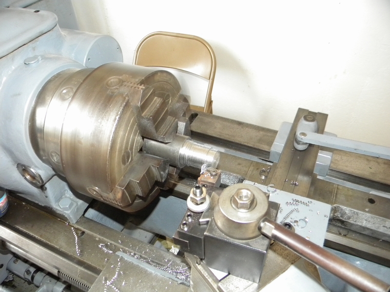
Installed on the lathe with a freshly cut QCTP clamp block ready for drilling. I have a BXA post that I will borrow from my DSG lathe for testing.
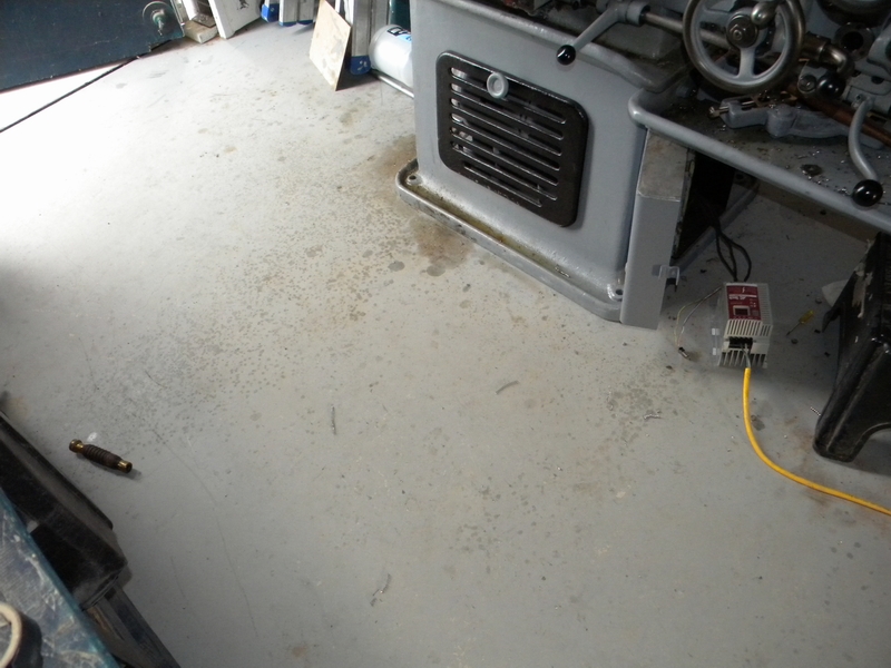
This shows the oil kicked out by the machine. Note also the fine VFD installation, I'll put that in a box later.
Finally its first cut . The lathe works good, however I did notice a bit of distortion at the end of a thread cutting operation when using
the auto disengage function while cutting threads to a shoulder. Most lathes do not even have this capability and it can be compensated for.