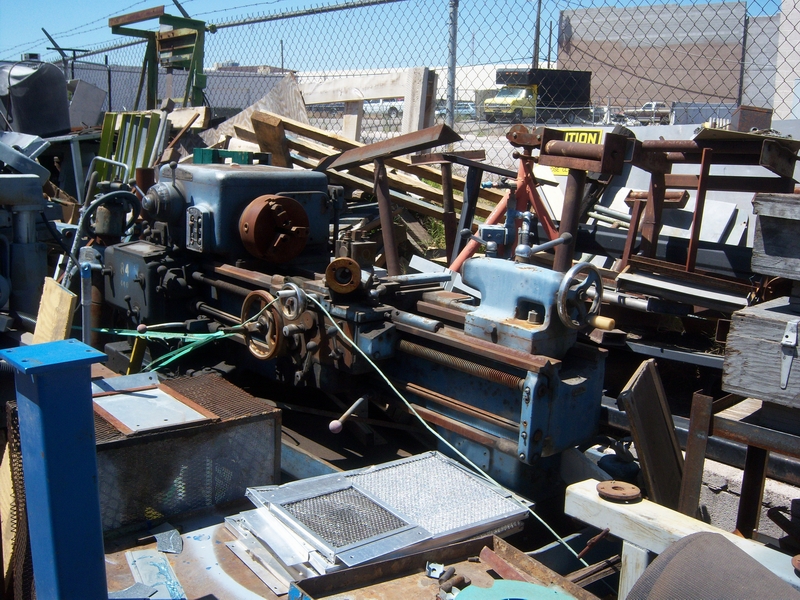
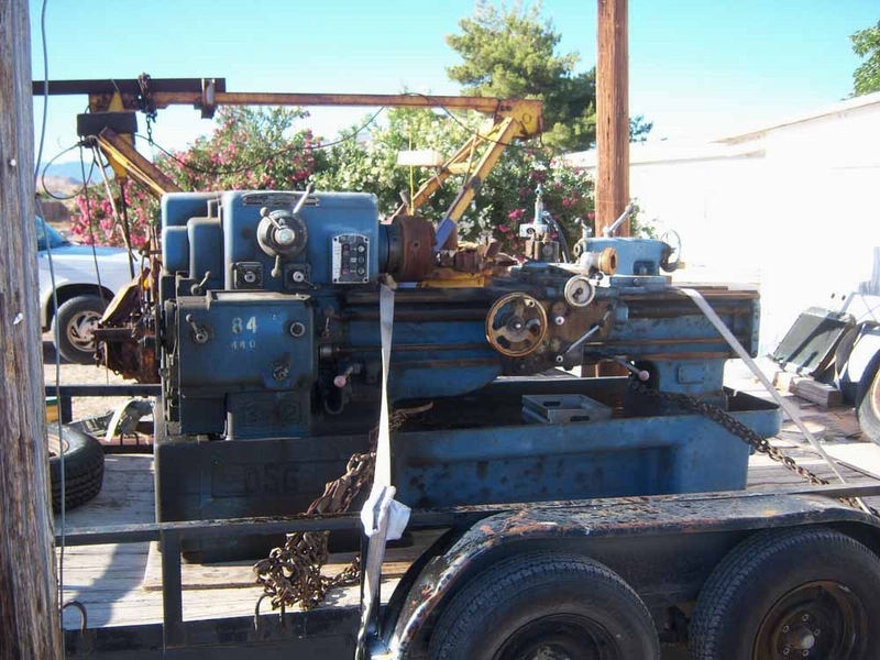
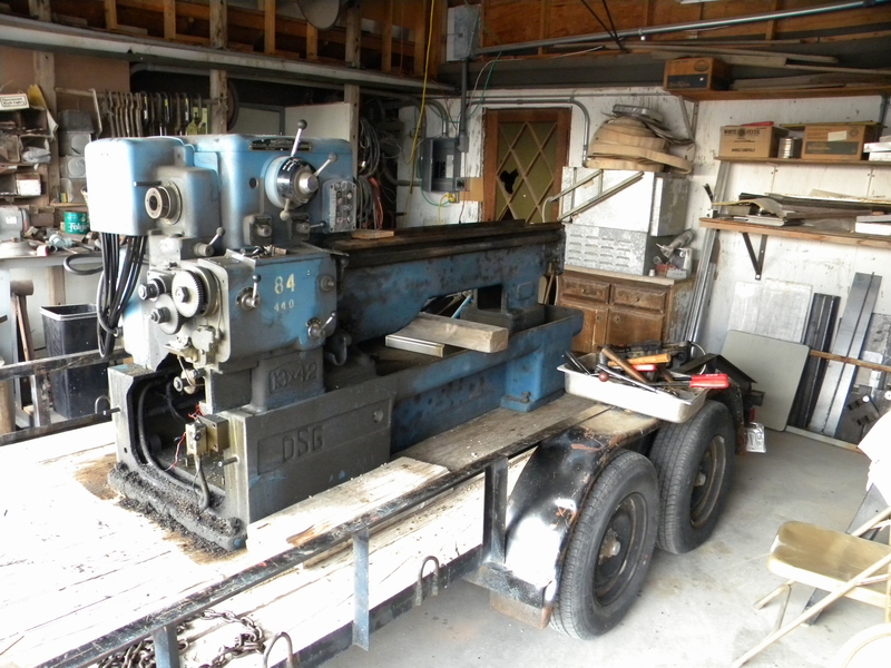
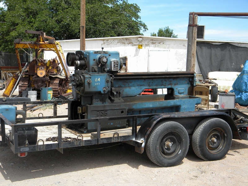
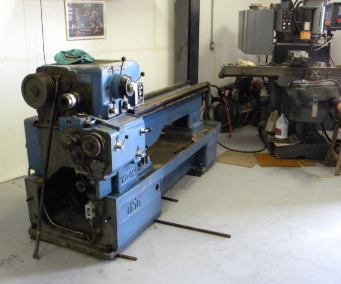
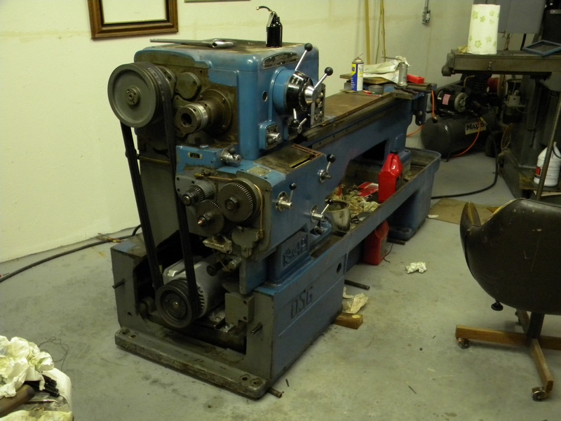
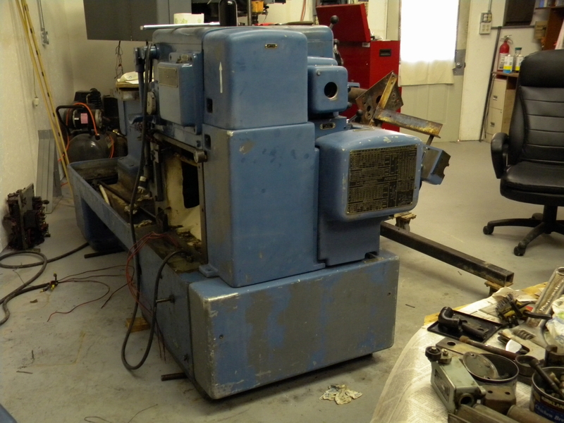
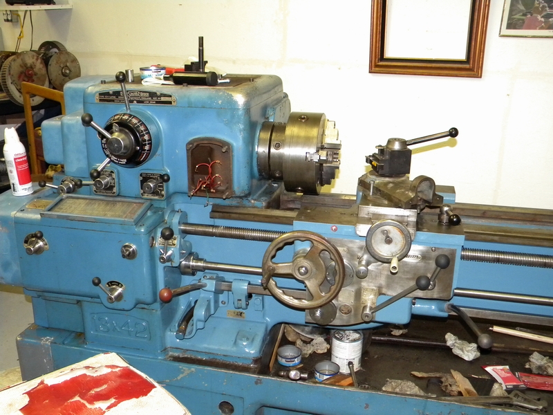
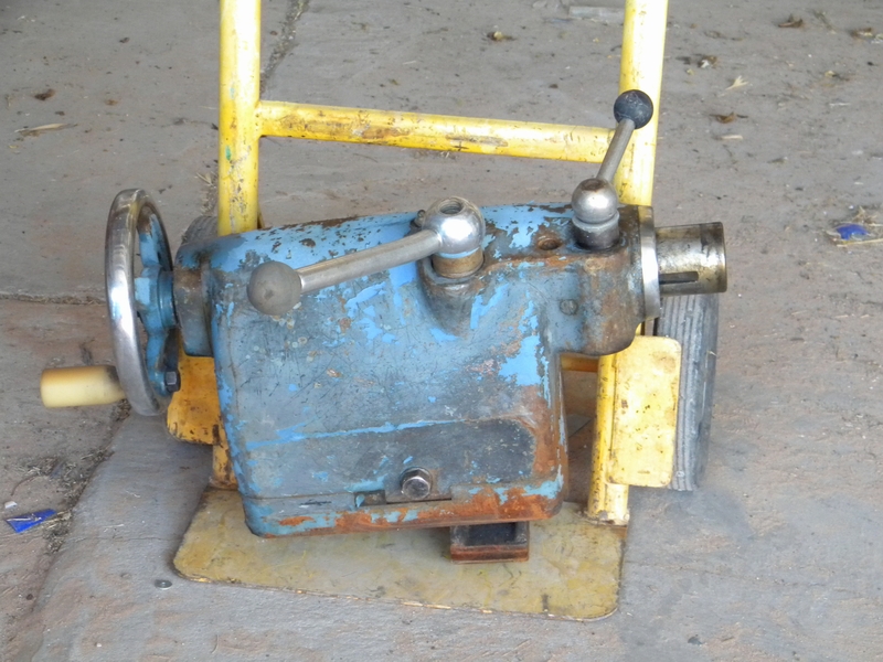
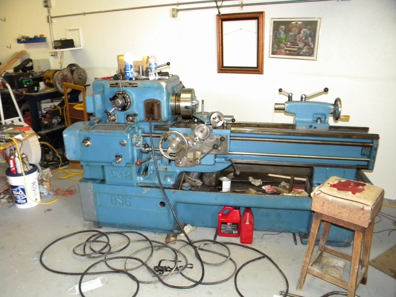
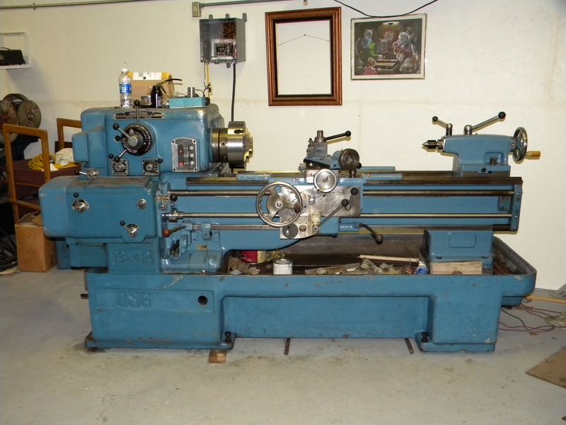
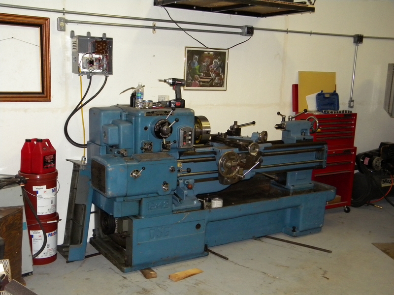
While browsing in one of my favorite locations I happened upon a 13" DSG lathe that was waiting to be made into Chinese manhole covers.
It had been abandoned out in the weather because the owner had purchased a CNC and it was no longer needed.
I had heard of the quality of the DSG and as I was looking for a heavier lathe than my 11" Logan I decided to see if This unit was available for a decent price.
After weeks of intense negotiations the machine was mine for a computer KVM switch and a scanner, installed of course.
The first thing that needed to be done was to make the trek to Vegas and pick the machine. This was a nice, 1 hour trip each way in 105 degree weather.
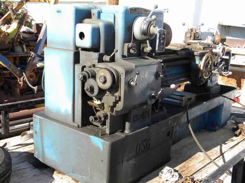
Finally got back though and started to access damages.
The lathe was filthy so the first thing was to get it ready for an initial hose down.
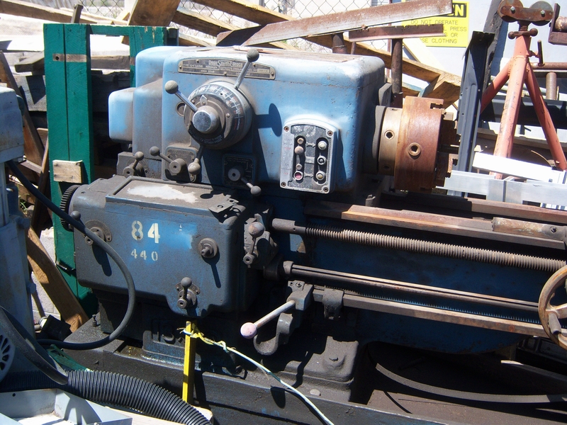
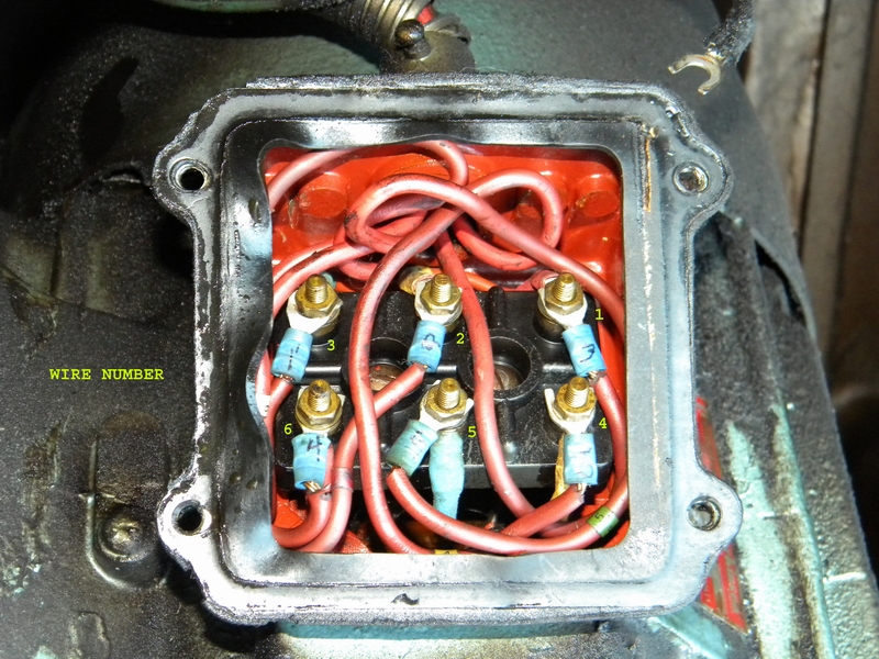
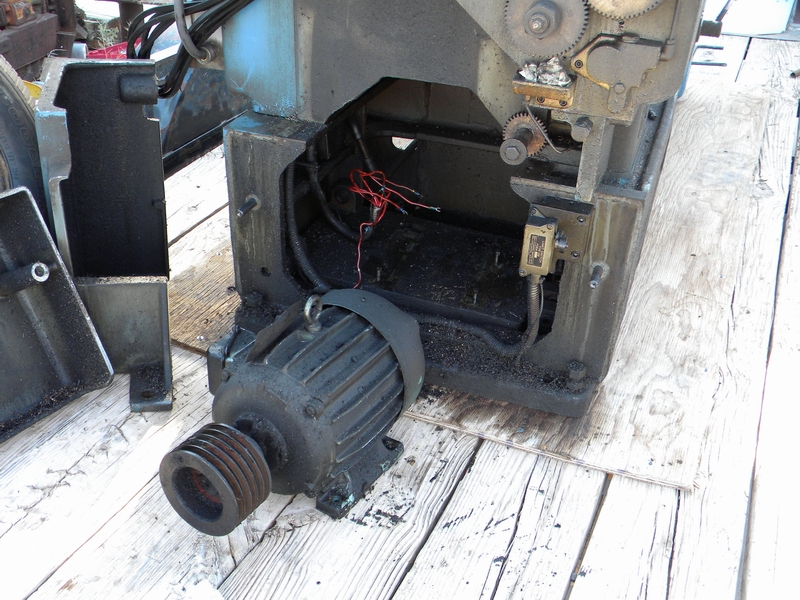
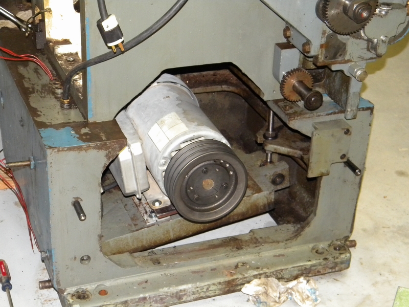
I needed to remove the motor (440 volt 3 phase 7.5 hp) so I could hit the unit with the Hotsy and degreaser.
I wasn't worried about the rest of the unit after what it had been through and it would be completely torn down anyway.
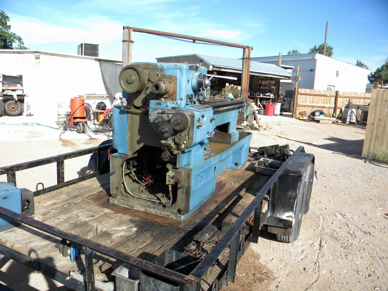
I popped the cover and documented the wiring as best I could but I'm thinking 7.5 hp 3 phase from my single phase capability might be a little much.
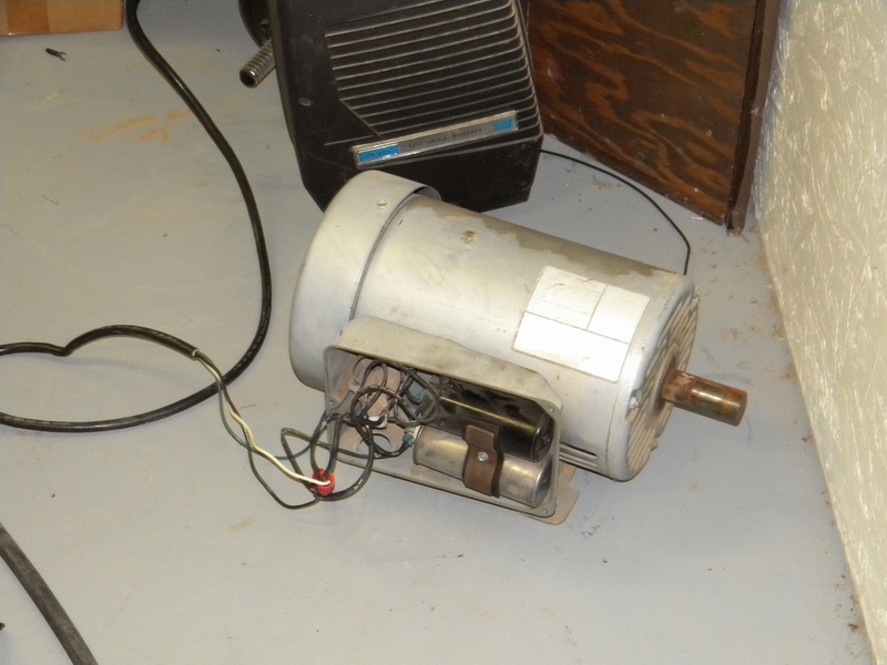
Besides I just happen to have a single phase 5 hp lying in the back waiting to be used.
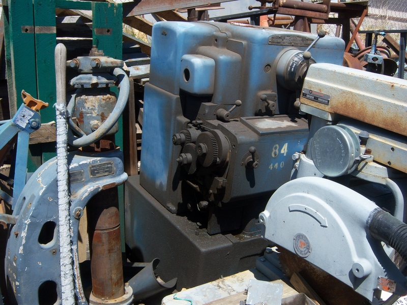
After pulling the machine into my welding area to get out of the sun (105 degrees, remember?) I pulled off the carriage and shafts for later cleanup.
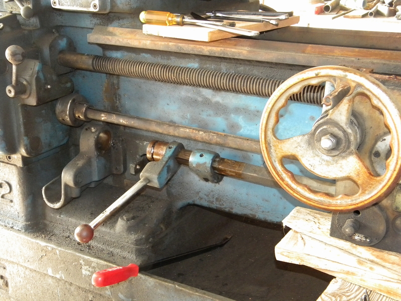
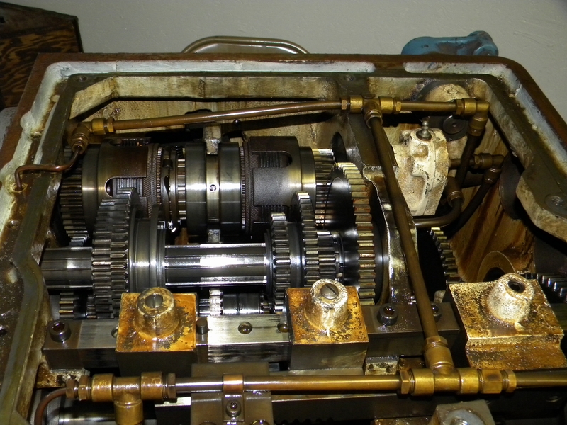
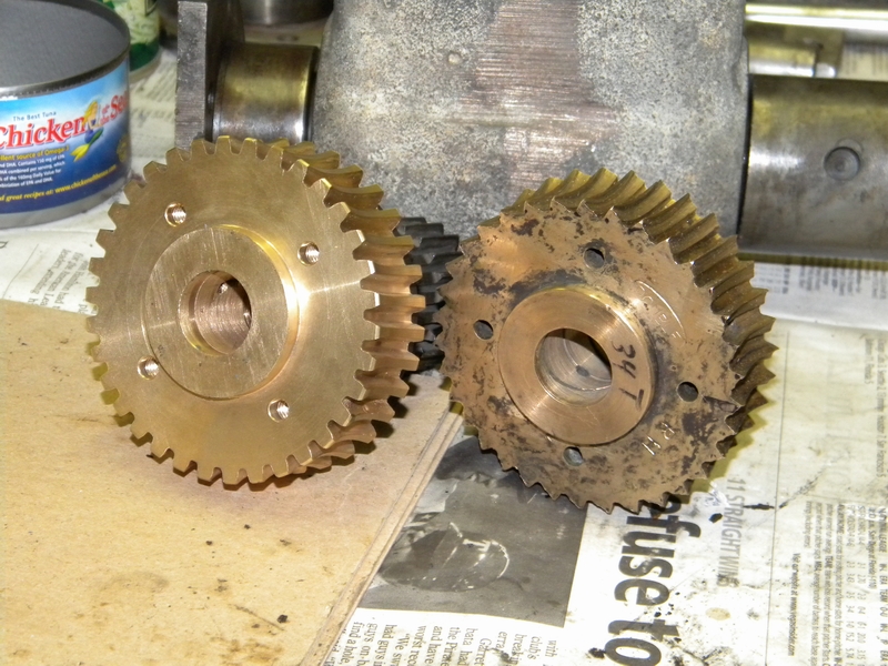
This is where I noticed the previous owner had used lots of grease instead of the necessary oil for lubrication, causing the worm gear to prematurely wear.
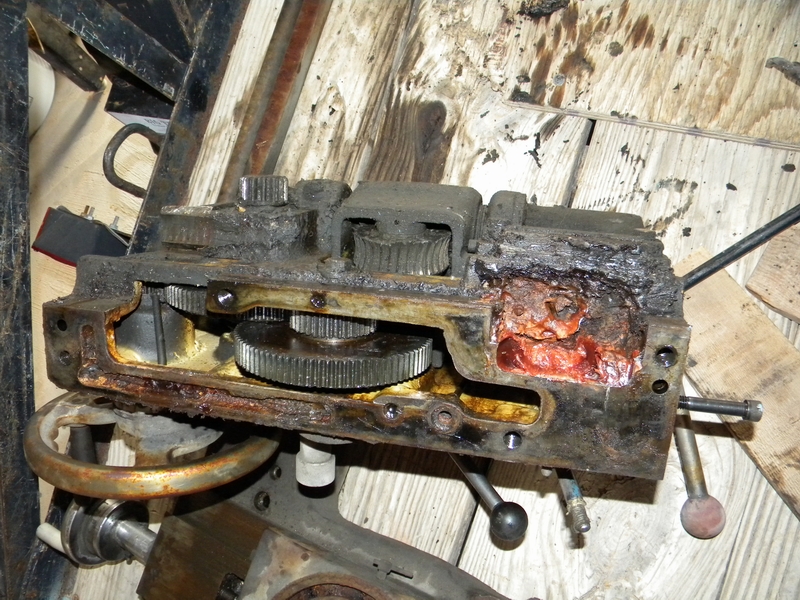
There is lots more to go including the saga of the cover, the cleanup and more on the gear.
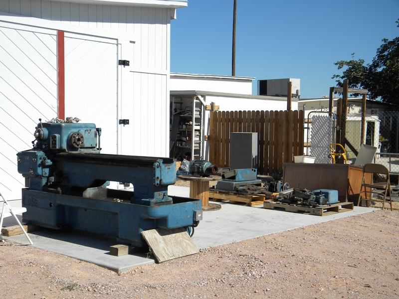
Back to the cleanup. Got it parked in the drive, 6 cans of degreaser in hand and ready to fire up the Hotsy.
A quick hose down and now the lathe can be touched without being engulfed in grime.
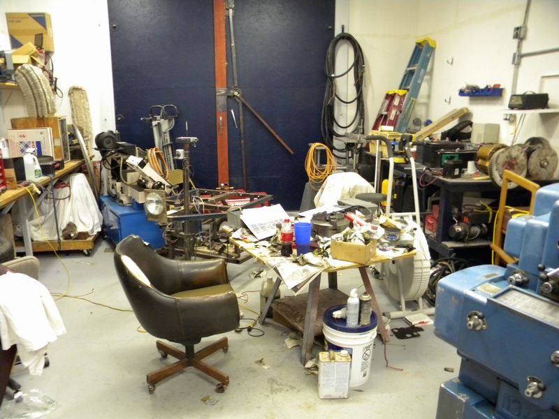
Now we can move to the other side of the farm and the real work begins. Here we are in the back of the big house.
That's what my grandson calls the shop I had to build to house my Shizuoka mill. That story is here http://www.kimfab.com/shiz/shiz.htm
The lathe had to suffer one more indignity. I removed the coolant pump, plugged the holes and filled the tray with a nice lye solution.
The cross slides then went in to soak in the hot desert sun. The rusty box in the background is my lye soak tank.
I have run many engines thru it over the years and they all come out nice and pristine. It ended up with the apron. At the end of a 116 degree day I measured 135 degrees in the tank.
I can already hear the screaming and the gnashing of the teeth "he put the apron and cross slides in lye? It's OK, I'll be giving them at least two more cleanups.
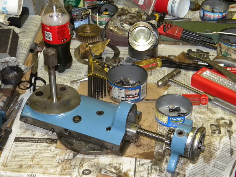
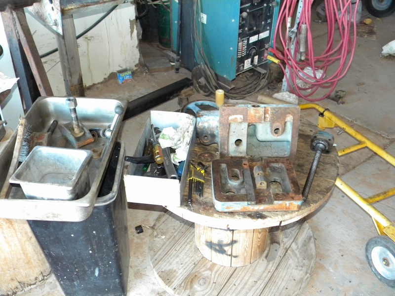
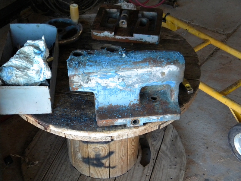
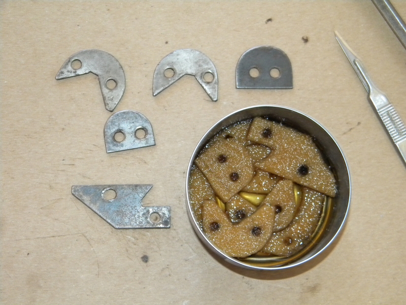
After soaking for a week and cleaning the main body of the lathe I started to take the smaller pieces out for cleaning. First up was the upper crosslide.
This cleaned up reasonably easily and was set out for final cleaning. I put all of the small parts in tuna cans to keep them together and prevent loss.
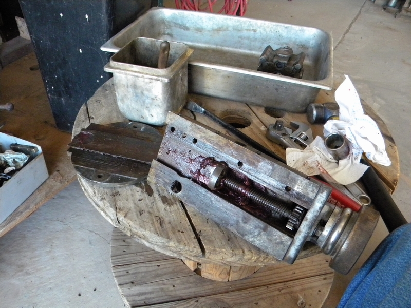
Next I tackled the lower crosslide. As you can see it has a broken piece. I'll probably end up making one.
Here is where I ran into some real problems. The gib was stuck and the screws would only turn about half a turn.
I ended up tightening the gib screws and running a bottom tap carefully in the holes. It finally came apart but I spent half a day playing with it.
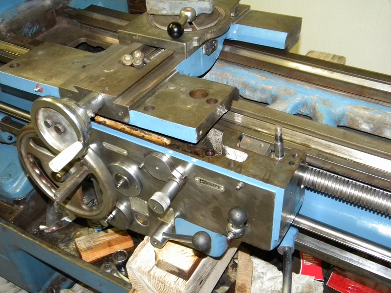
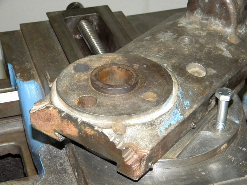
The apron was too heavy for my back so I made a bracket for it to mount on an old engine stand. Then I spent a half day tracking down and cleaning oil holes.
It seems the Bijur oiler on the front of the apron is only for oiling the longitudinal ways. It comes out of the bottom, thru a copper pipe and up to a hole in the mating surface. (green)
Another five oil points are fed from a reservoir that is filled from a top oil point. (blue)
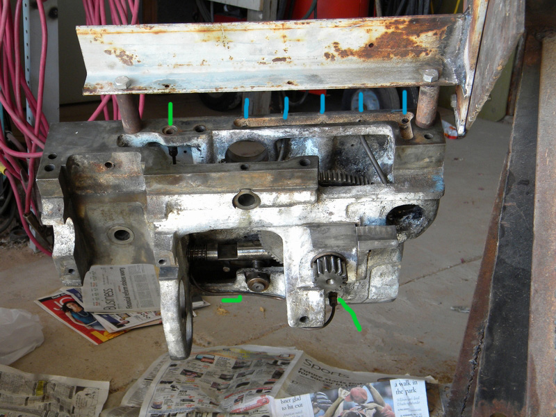
As expected it got nasty again when I flipped the apron over. The oil from the pump comes up to the apron (green) and down a long, gunk filled tube to holes positioned over the ways.(red)
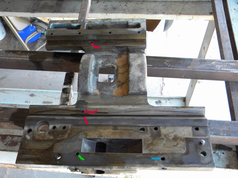
It was a long procedure of shove a wire in, pull it out, rinse, and repeat. Took quite a while before it came out clear.
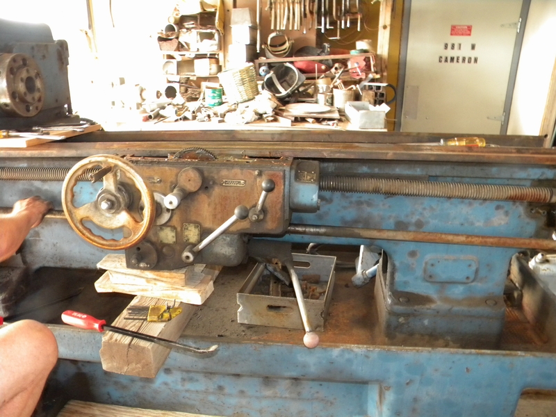
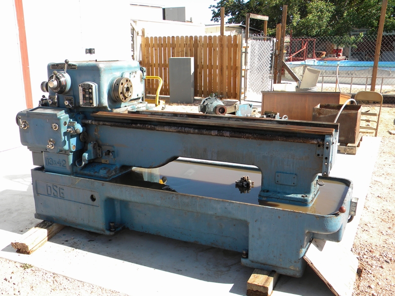
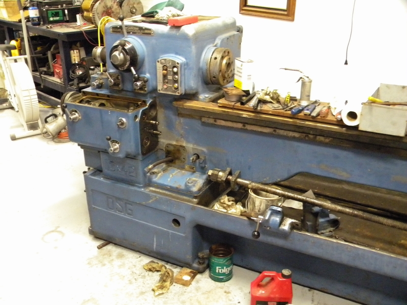
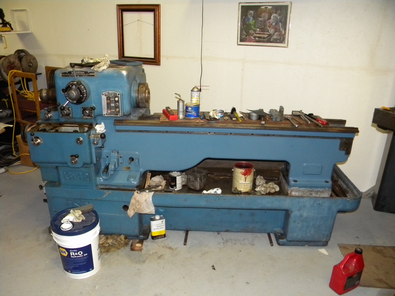
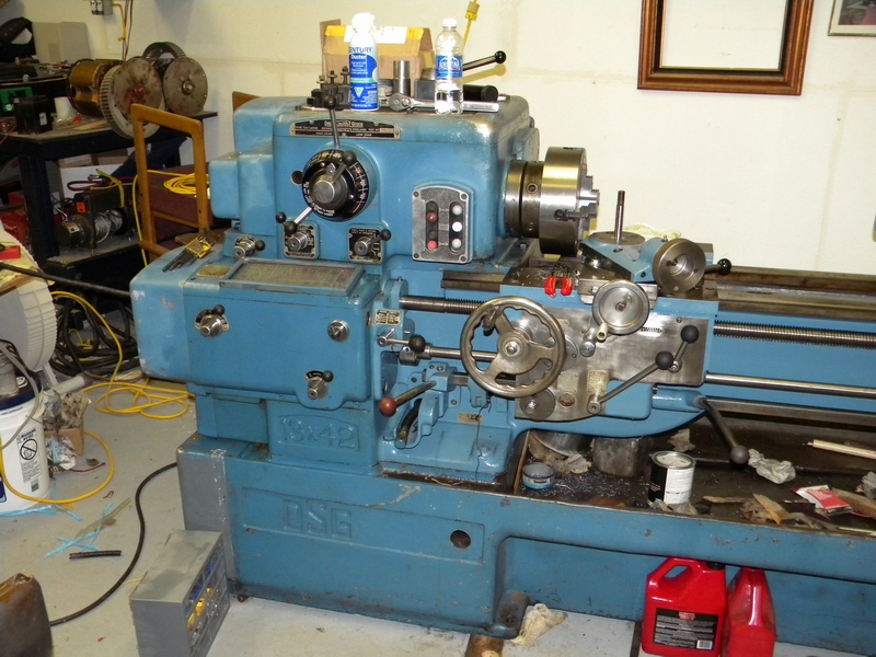
Finally cleaned an area in the big house and dragged the lathe inside where I can work in air conditioned comfort.
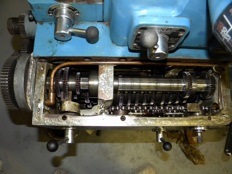
I opened up the transmission for cleanout (it was half full of water) and removed the leadscrew and drain spout.
Luckily the only damage was a lot of fluffy oil-water junk that I got rid of with an alcohol spray rinse and several Marvel oil washes.
I then filled it with some cheap hydraulic fluid and Marvel. After I run it a bit like this I''ll drain, rinse and fill with the proper oil.
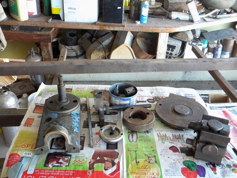
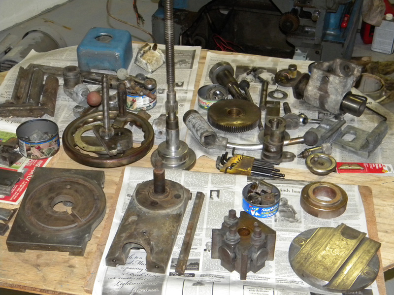
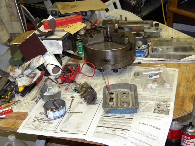
Got all the parts laid out for the final cleanup and assembly.
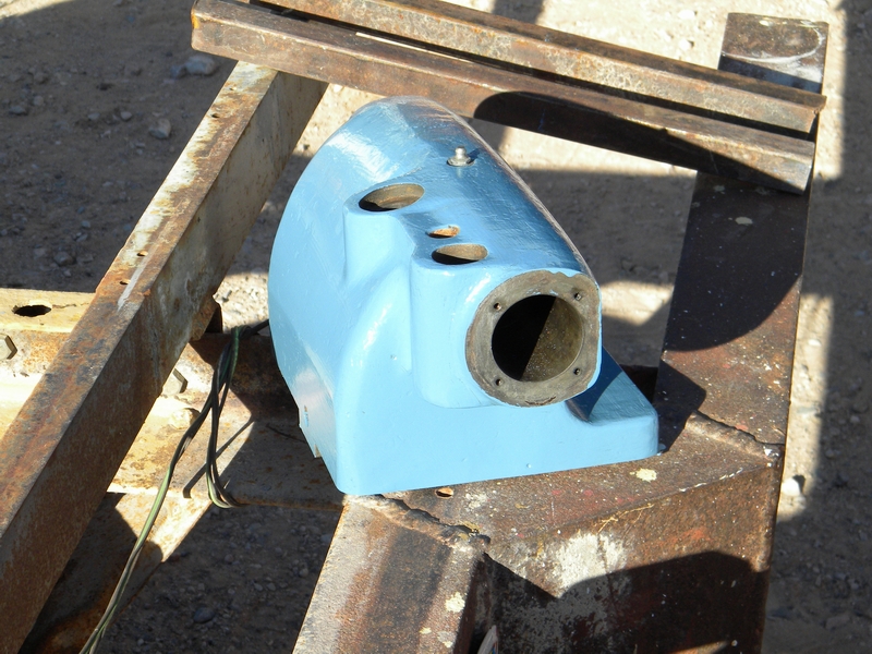
Removed the rack gear, cleaned up the side and reinstalled the transmission side cover. A quick shot of paint here helped make it look better.
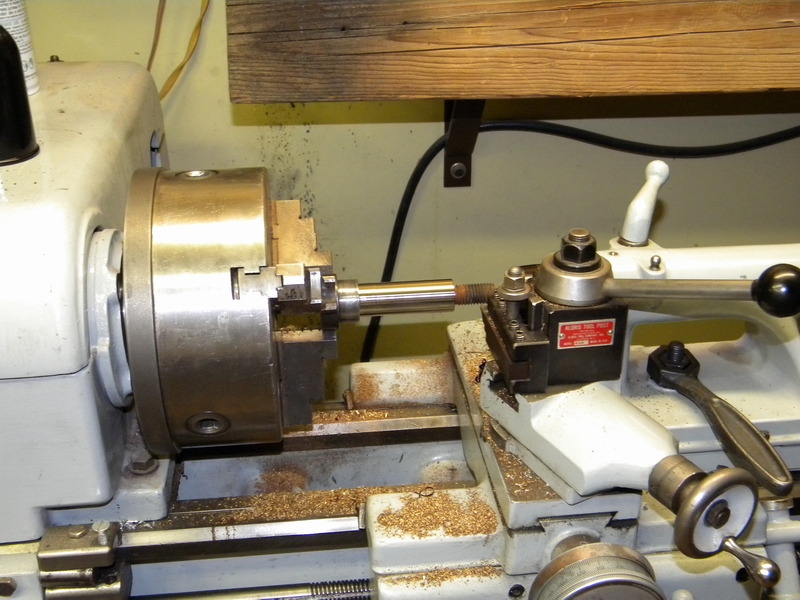
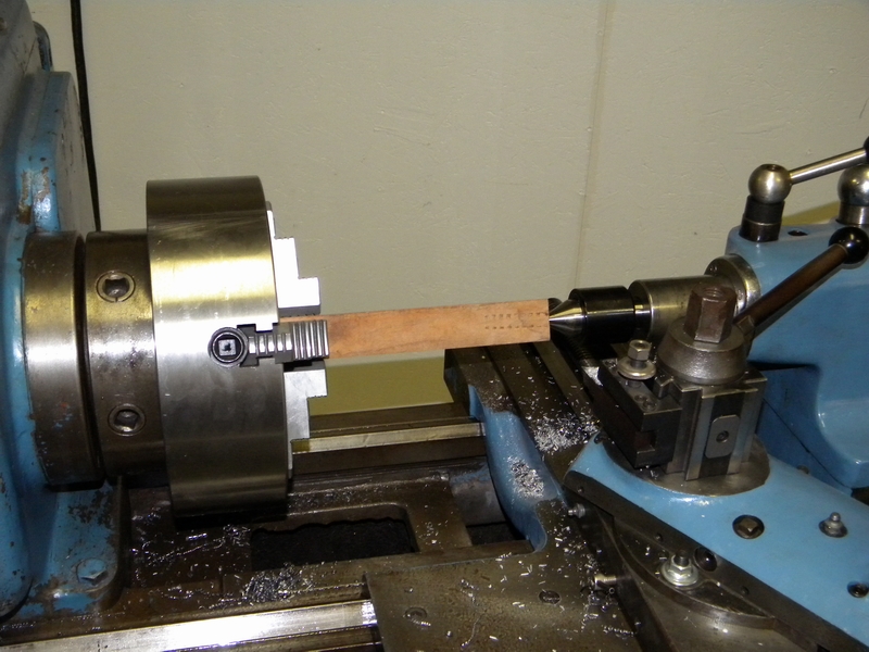
The bearing for the feed shaft is worn pretty bad so I'll have to make a new one.
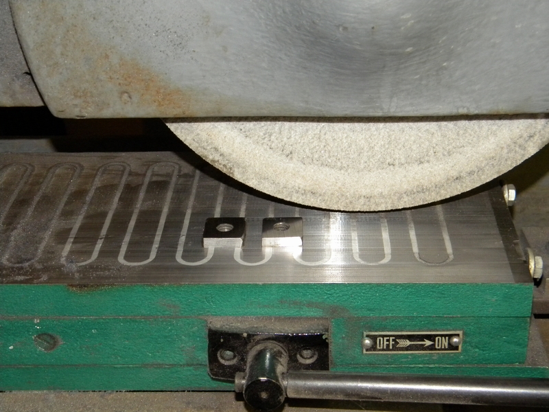
Got the shaft chucked up here for its cleanup on the bearing surface. I mounted the bearing block on the Lagun so there was no whipping of the shaft.
Back to the machine. Pretty much gutted the electrical. I will be reusing the front panel controls so that wiring was left but the relay plate
was removed for possible later use.
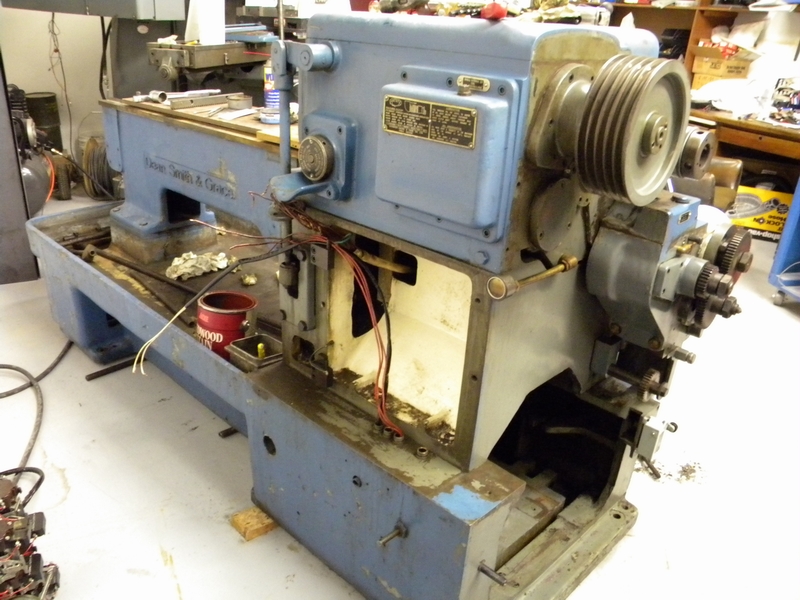
The original 7 1/2 hp 3 phase motor was a bit much. I didn't need that much power and I didn't want to spend the money necessary to run it on single phase.
I already had a good single phase 5 hp in stock waiting to be used. All I had to do was figure out how to make it turn in the right direction.
Got the motor running OK but with the new pulley it did not line up with the one on the lathe and there was no adjustment.
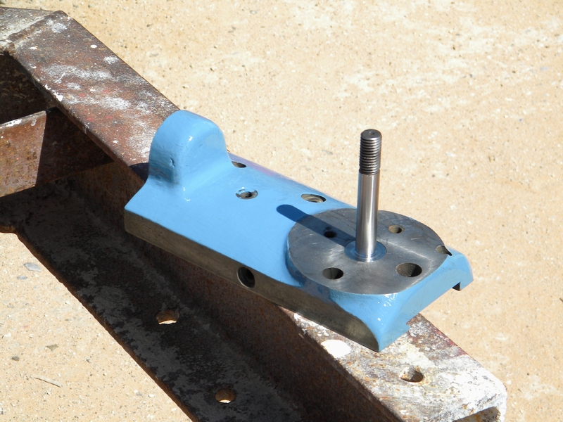
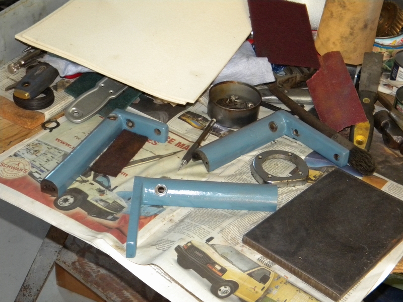
A chunk of 1/2" plate and some angle, a few welds, some milling, drilling and tapping and we have a DSG approved adapter plate.
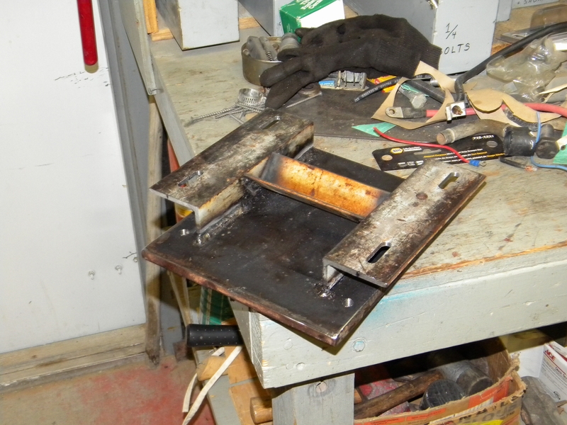
Mounted up, temporarily wired in and ready for the belts.
Next up is the headstock. I was concerned about the appearance of the clutches but after oiling them up and trying them by hand they seem to work OK.
No water here but it obviously needs a few rinses. While I was doing this and checking the pan I found a loose bolt lying in the bottom.
Took a bit of fishing to get it out and I couldn't see any place where it would have come from.
Got the belts hooked up and adjusted. Received the oil gun and primed the pump.
Time to fire it up. I left the cover off to see if it was oiling properly. Big mistake. Nothing wrong with the oiling system. Here is the action flick.
http://www.kimfab.com/pictures/DSG/lathe272.avi
That is without the gears turning and throwing oil too!
The transmission is a little quieter. Big file.
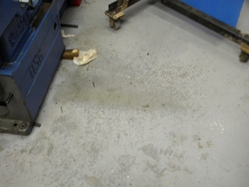
http://www.kimfab.com/pictures/DSG/lathe273.aviHere is the floor after the test run.
Now that I know it works I didn't like those belts and gears whipping in the wind. Time for covers.
Got the replacement gear in so it's time to assemble the apron.
Finally got the apron back together and ready to mount.
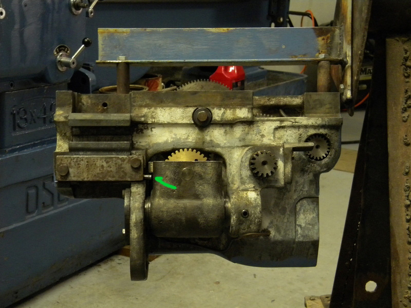
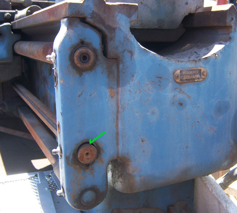
The green arrow points to the lockout pin. This keeps the feedscrew and the leadscrew drives from engaging simultaneously.
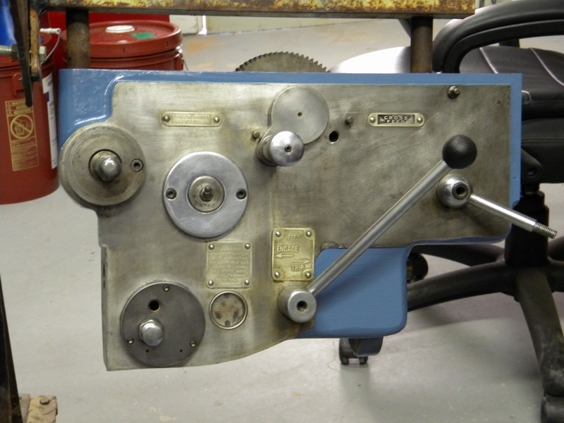
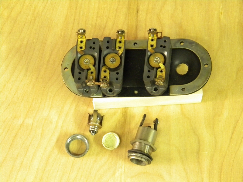
Onward to the control. Took off the front cover. The indicators will have to be replaced. The switches look crude but usable.
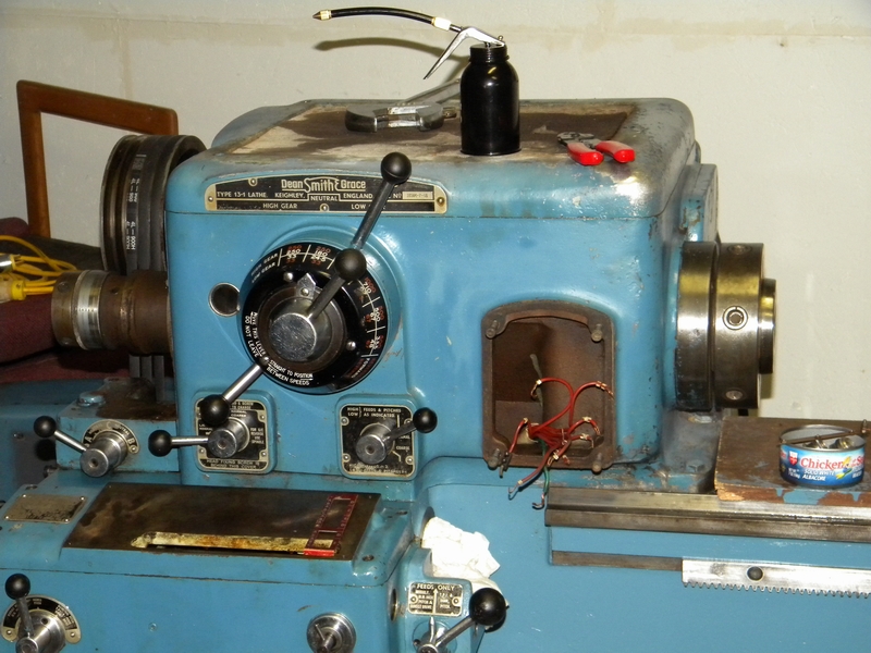
Here are the contacts.These need a cleanup but the lenses in the indicators are either dull, missing, or broken.
The bulb holding method is not too impressive either. Got some replacements on order.
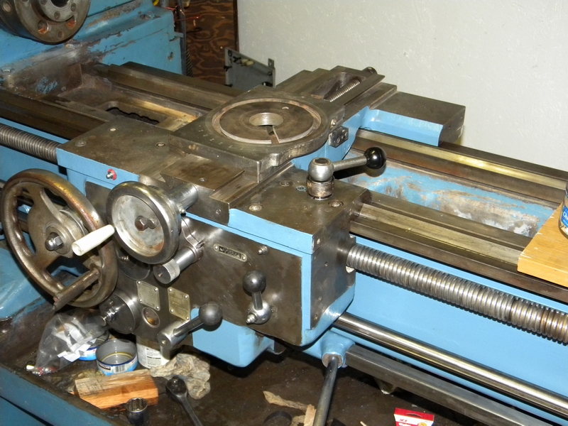
Finally got the apron on. Took most of the day to hook up all the shafts and levers. Ran it thru the gears and it seems to feed properly.
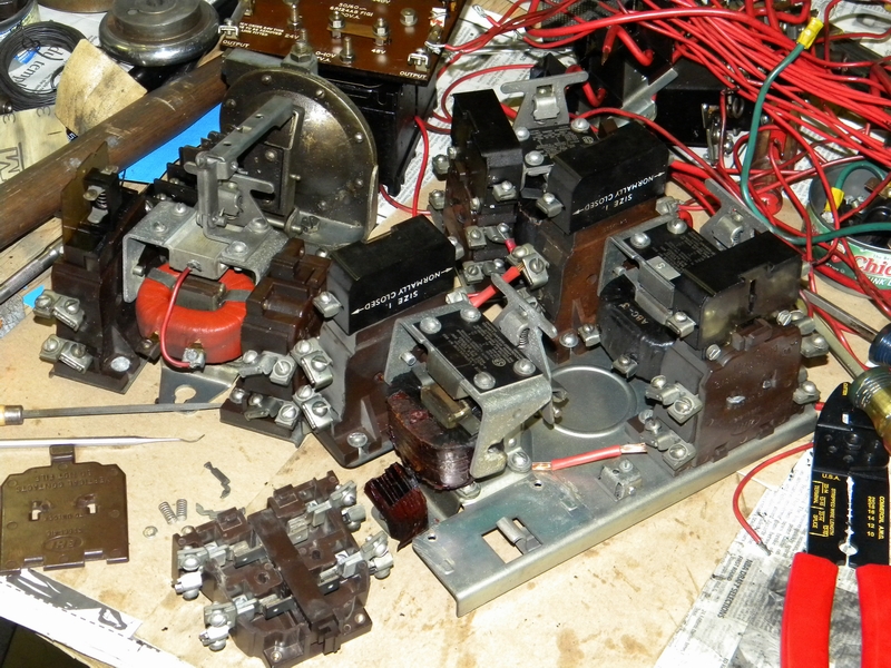
Now work on the saddle, cross slides and control relays can begin.

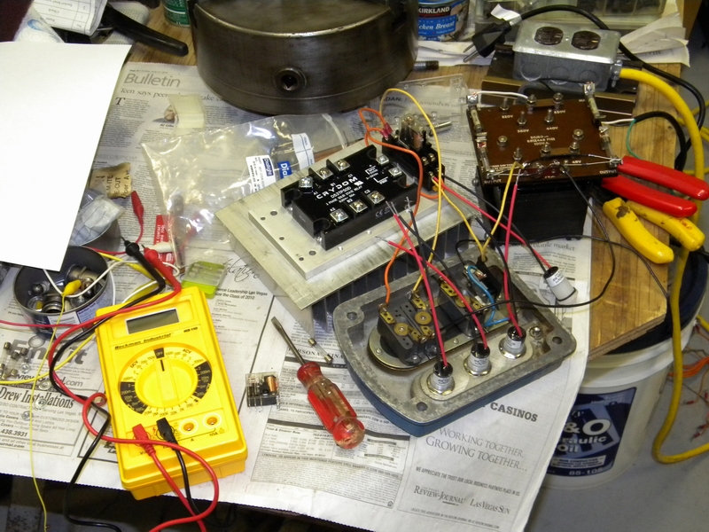
I had the delusion after looking at the relays that I could reconfigure them and reuse them. Wasted a whole day taking them apart and
checking and cleaning them. I couldn't get them to pull up properly, looks like bad coils all around. I'll use solid state relays instead.
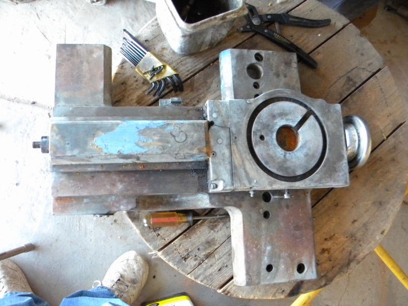
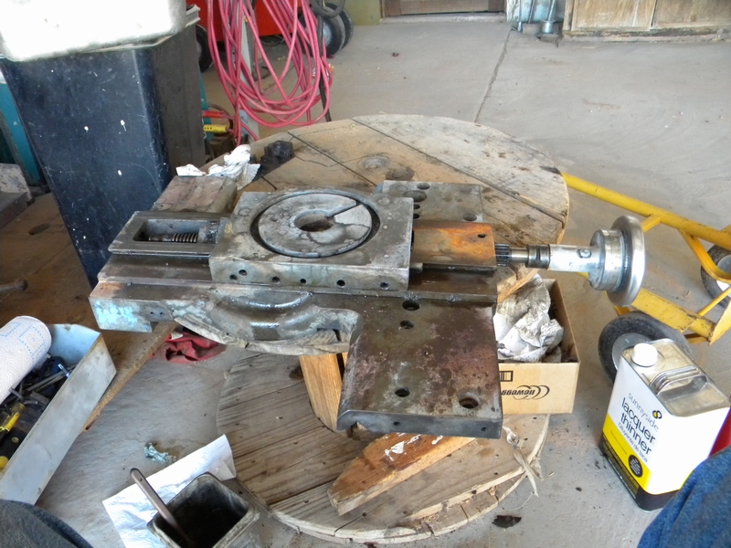
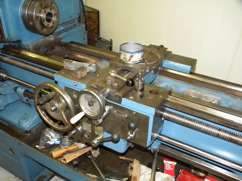
Back to the saddle and cross slides. Got the lower cross slide figured out and installed and it's time to take the saddle off again to
install the front gib plates and the saddle lock.
The left gib plate will install OK but the saddle must be raised for the right gib and the lock. Throw a brace under the apron to hold it
and lift the saddle.
Back together again. Takes a bit of fishing to get the gib and lock lined up and bolted and then the left gib slides right in.
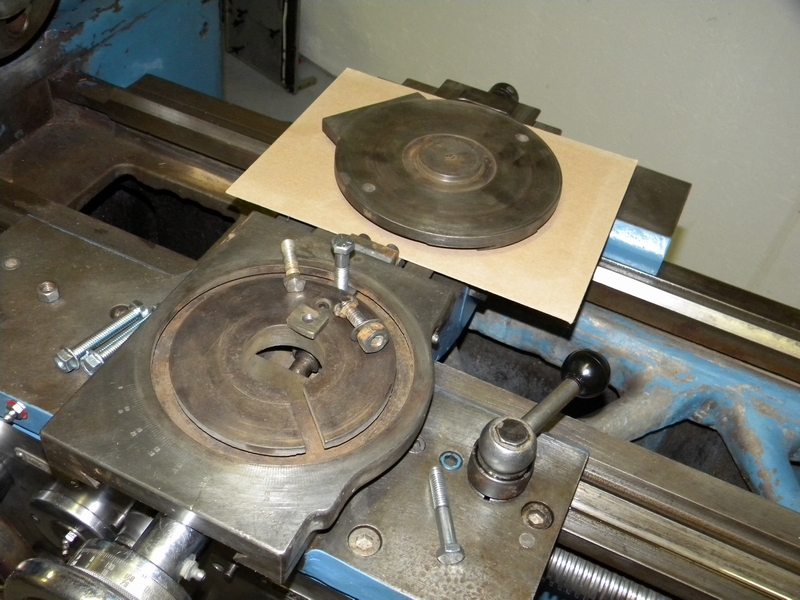
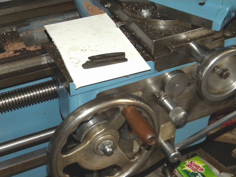
The unit used to set the angle of the top cross slide was held down with a couple of cobbed up bolts so some new clamp pieces had to be made.
Here are the sliding clamp pieces along with the cobbed up bolts they are replacing
Now that the top cross slide can be installed there is a new problem. toolholders for the original Dickson toolpost are expensive if they can be found.
I decided to use an existing BXA post, however there is a height problem. Even with a holder at its lowest point, the cutter is too high.
This requires a high level management decision. I hate to cut the boss down on the crosslide but that seems to be the only way to make it work.
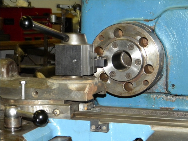
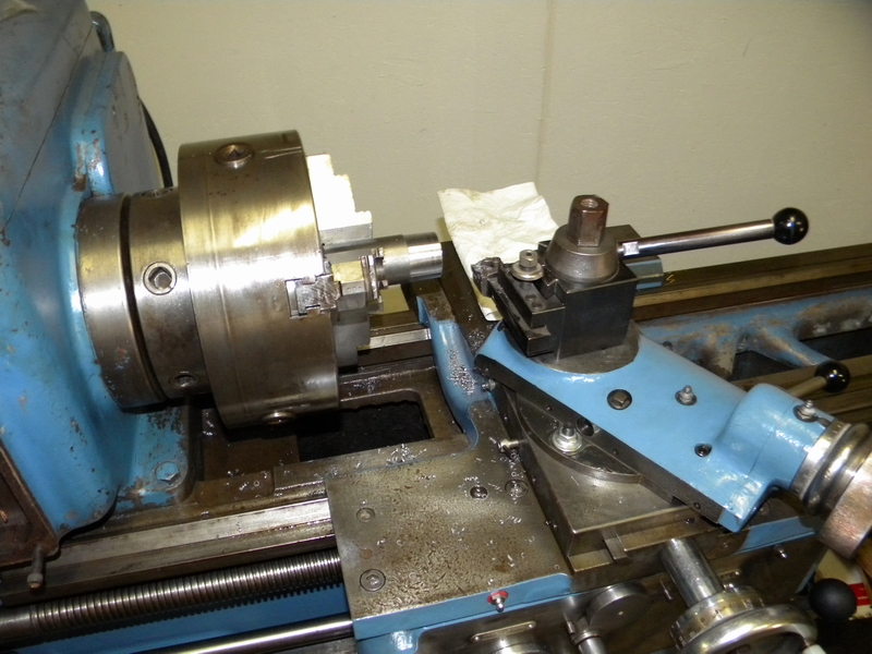
Decided to work on the chuck while I pondered the height problem.
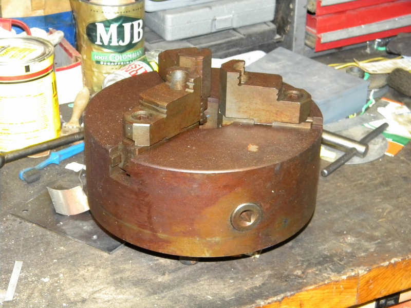
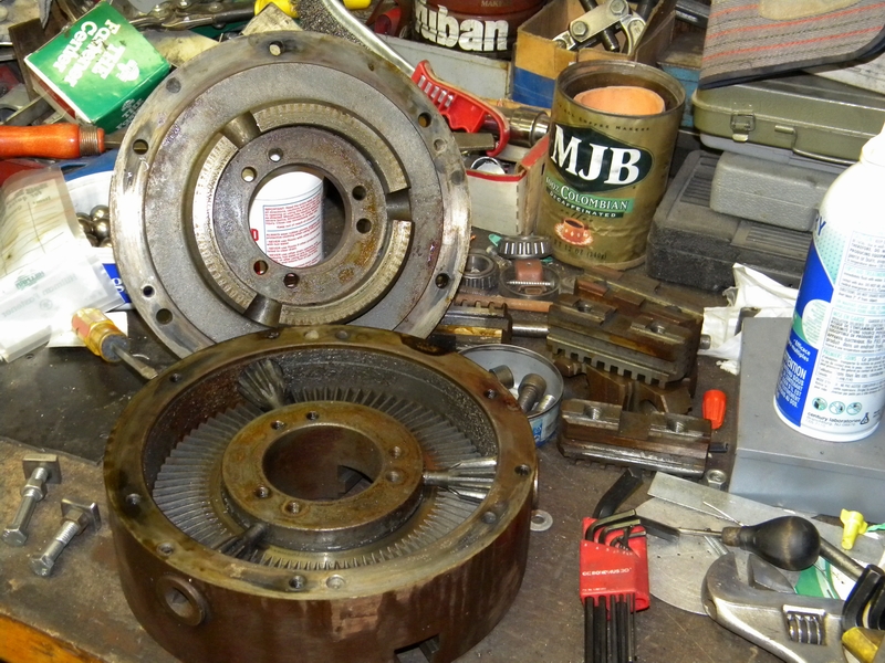
Chuck came apart easily, not too bad inside.
Had to clean up the D1-6 camlock setup. It was covered with oil and gunk.
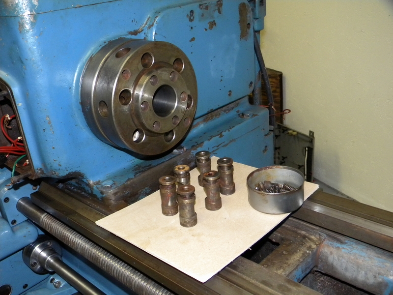
Back together and the finished chuck is mounted. Now for the top cross slide.
Decided to bite the bullet and cut the upper cross slide down. Here it is before.
Here is the after. I also cleaned up the nicks.

Next turn the post down.
Painted and set on the trucks back bumper for a nice 110 degree sun baked finish.
Got a solid state 530 VAC 3 phase relay from my son. I'll use 2 legs of it.
My heat sink was a little light on the backside so I'll use a piece of !/4" aluminum for better heat distribution.
Assembly of the top crosslide.
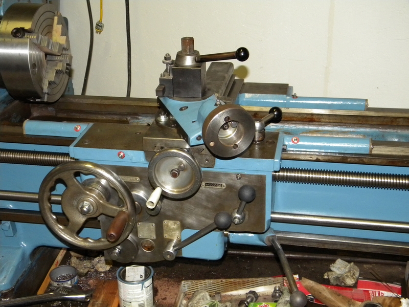
Mounted with tools.
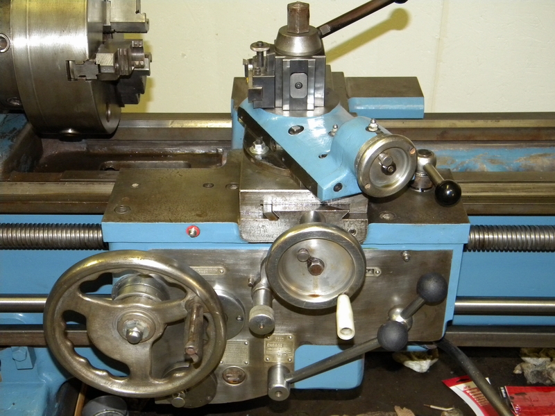
The first cut. Still a lot to go but it cuts nice and smooth.
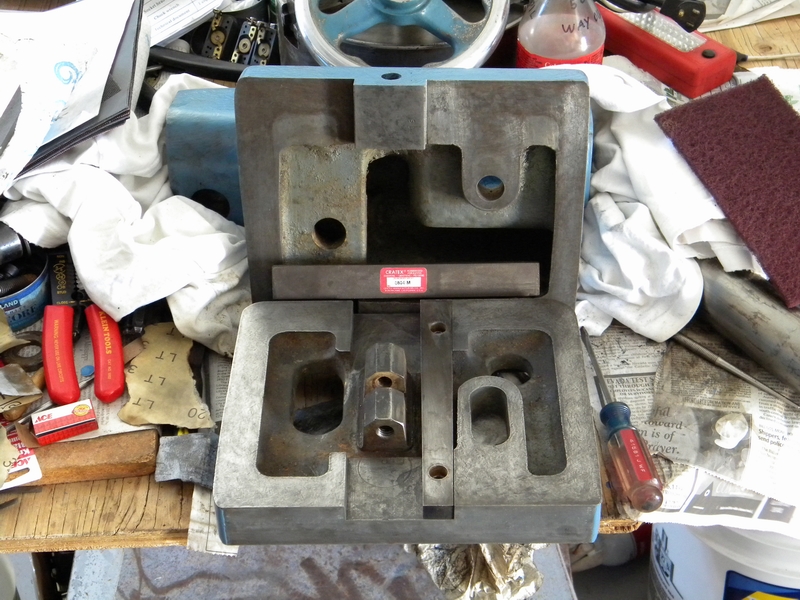
Next up is the tailstock
The center adjustment opened up . A lot of surface rust but no pits.
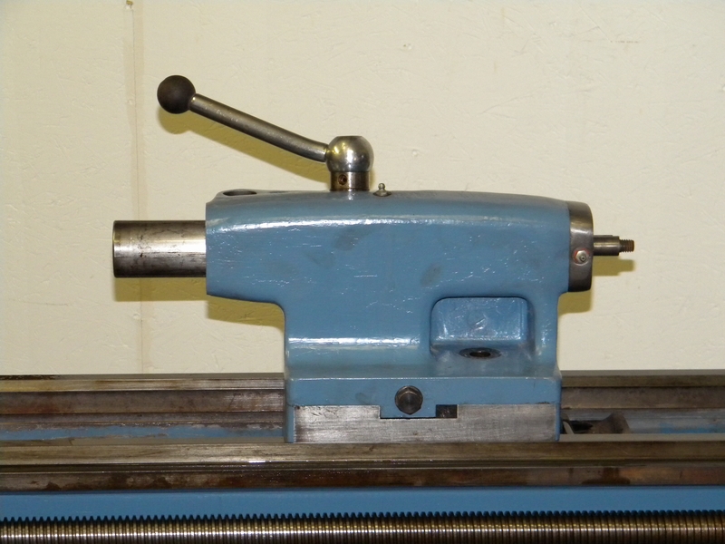
Scraping off the old paint.
Painted and set in the oven to bake.
Starting to clean the mating surfaces. I scraped the rust off with a razor blade and then a light touch with a Cratex.
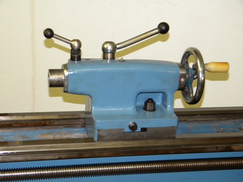
The top and bottom mated on the lathe. Main hold down and screw installed.
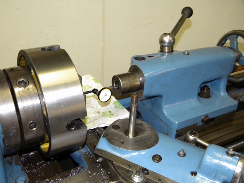
Indicating in the tailstock. Got it good front to back but it is about .006" low.
Ready to go. Now I need a #3 Morse center and perhaps a drill chuck or two.
Got the lathe's main components in place and operational. Now for some prettiness. Clean up the mess first.
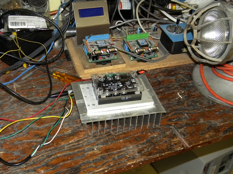
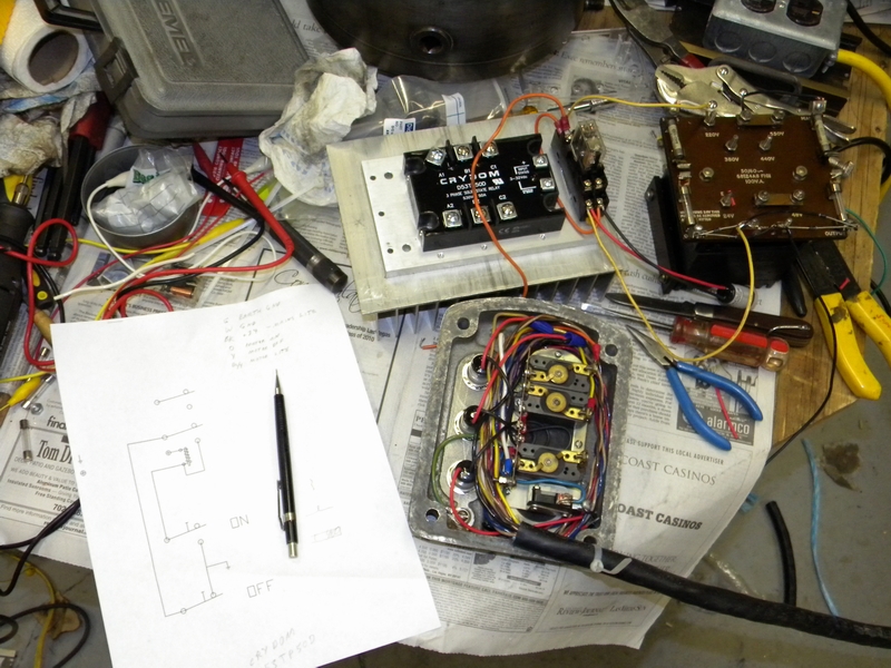
Laid out the main electrical components. I got replacement LED's that fit right intothe old light locations. Cleaned the contacts on the push switches.
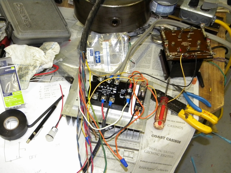
Mounted diodes on the transformer and assembled the heat sink, buffer plate, and solid state relay.
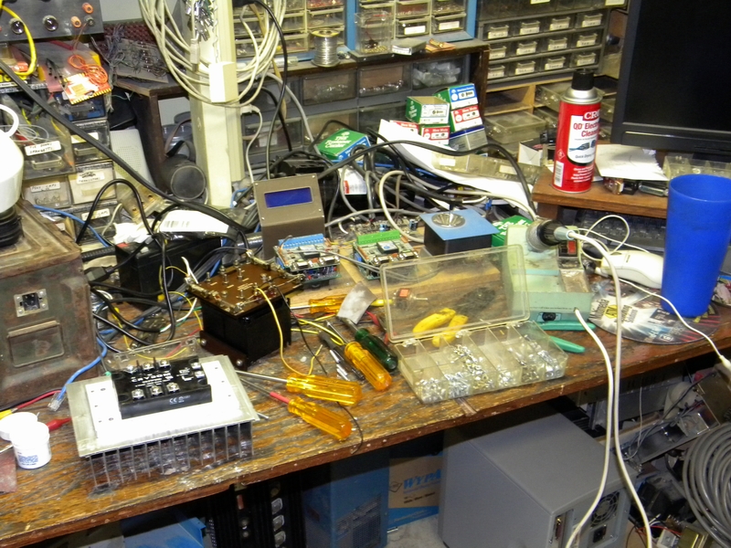
Wired together on the bench. Seems to work fine. Found a nice little DPDT relay with a DIN mount that fits nicely on the heat sink.
I used the classic 'momentary on, lock up to ground with momentary release' configuration for the circuit.
Found some nice heavy cable to replace the old wiring to the control and pulled it in.
Got the faceplate wired and ready to install.
Other end of cable including the solid state relay and transformer. Now all I have to do is put this end in an enclosure.
Faceplate installed in machine. Lights and pushbuttons work. Now I can start it from the front panel.
After running for 10 minutes and a dozen starts and stops there is no noticable heat from the heat sink.
Got a box for the control equipment. Put in some vents for cooling.
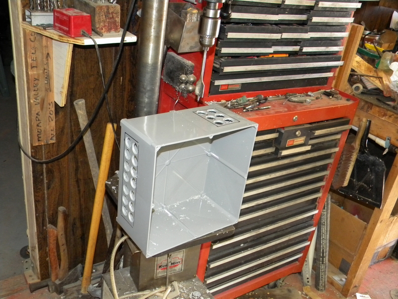
Everything fits nice.
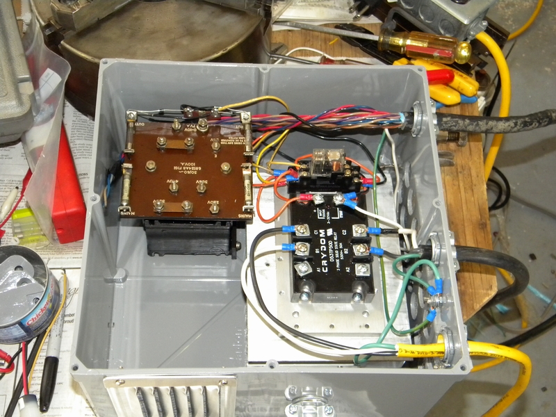
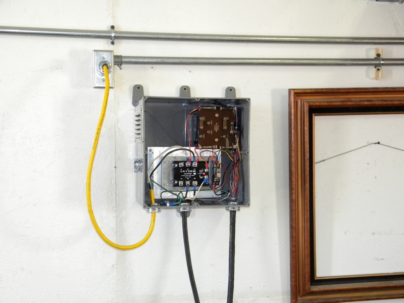
Mounted up.
The main relay died after some more testing. Oh well, it was a free non-working sample. Ordered up the right unit.
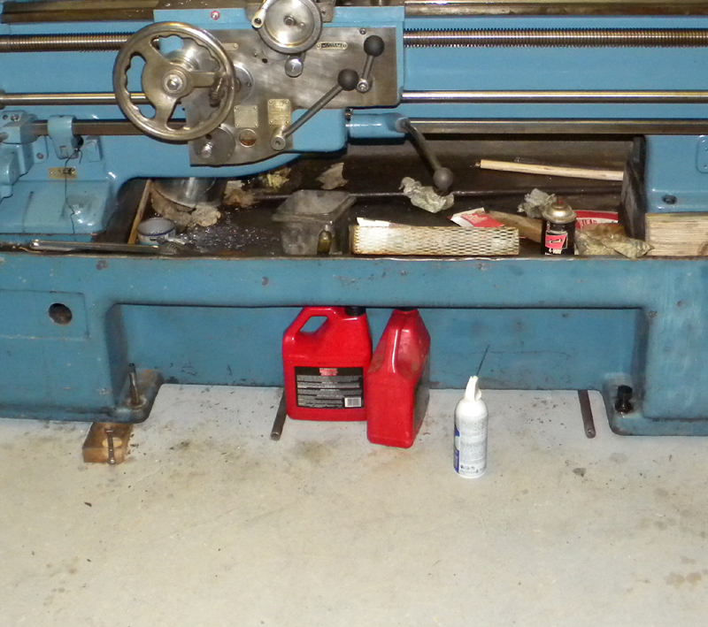
While I'm waiting for stuff I started retapping and cleaning up the leveling screws.
Mounted up a chunk of walnut for a new knob.
There, a nice walnut knob to replace whatever it was that was there.
Painted up the followers and got some #1 white felt for wipers.
Cut the wipers and soaked them in oil before installation.
All mounted up and ready to go.
Now that the lathe is basically ready it's time to slide it up next to the wall.
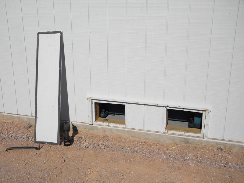
Because the level adjustment would be inaccessible I needed to install adjustment ports in the shop.
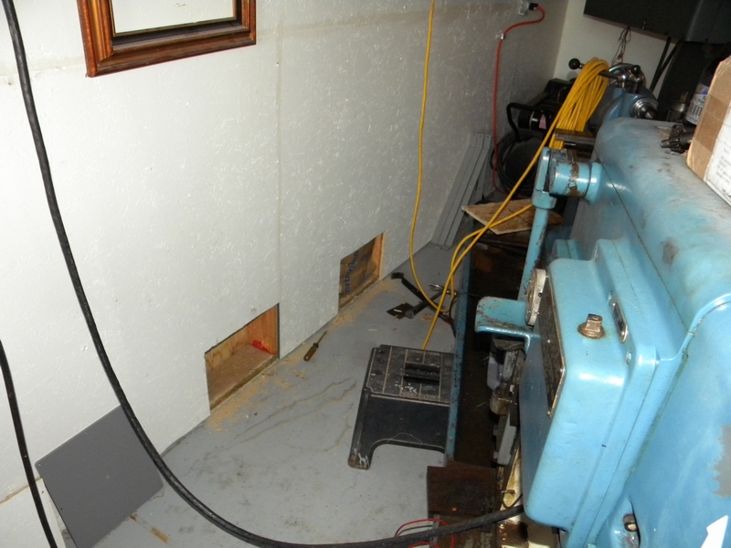
The ports are covered with a weatherstripped panel on the outside.
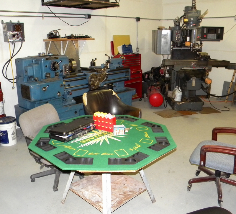
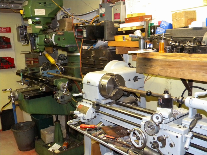
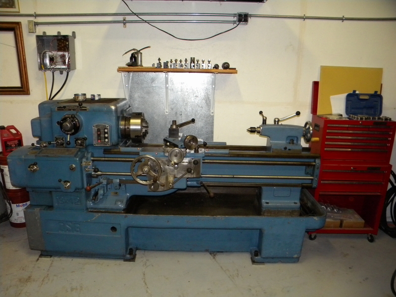
Finally in place. The shop is much bigger now.
I added a metal backplate and a shelf. The adjustment screws were set on 4 X 4 X 3/4" pads.
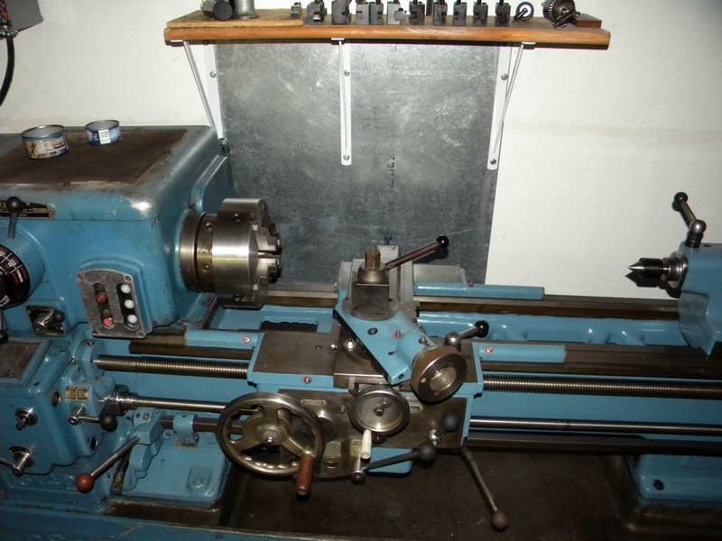
A view from the top. I still have to make a transmission shift knob, the broken piece on the crosslide and redo the headstock cover.
There is a number of other things necessary but they can be done after the cash jobs and with the machine in place.
Now we're ready go with the area decent and the makings of the annual invitational Thanksgiving poker party in place.